Flush mount – Airmar GH2183, GPS & Heading Sensor User Manual
Page 10
10
Flush Mount
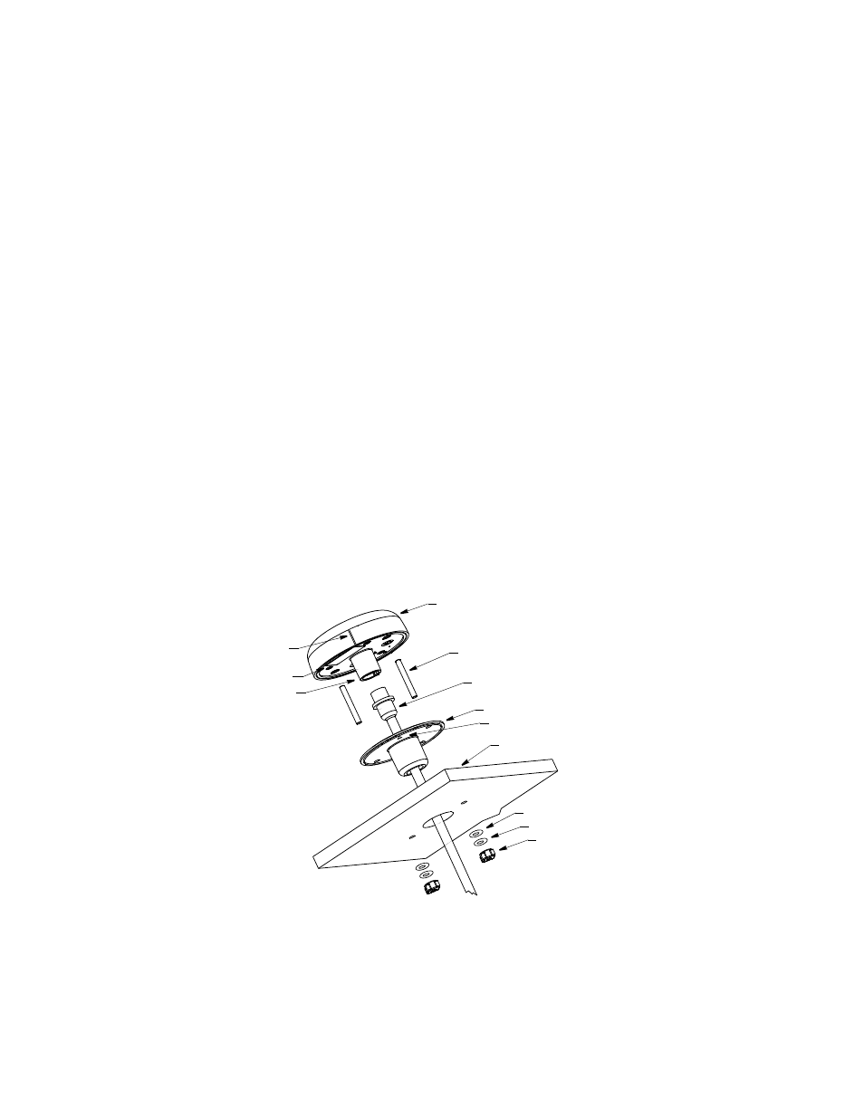
1. Remove the label from over the sensor unit’s socket (see Figure 3). Apply
removable thread locker to the two studs supplied. Screw the studs into the
underside of the sensor unit (part A).
2. Using the gasket (part B) as a template, position it at the selected mounting
location upside down with the arrow facing forward and parallel to the centerline
of the vehicle/boat. Mark the position of the two mounting holes and the center
hole for the cable.
3. Using a 3mm or 1/8" bit, drill the pilot holes. Using a 6mm or 1/4" bit, drill the two
mounting holes for the studs. Drill the cable hole with a 38mm or 1-1/2" hole saw.
Fiberglass—Minimize surface cracking by running the drill in reverse until the
gelcoat is penetrated.
4. Pass the sensor connector-end of the cable through the center of the gasket
and through the center mounting hole in the boat/vehicle.
5. Plug the cable firmly into the sensor unit.
6. Orient the gasket with the arrow facing in the same direction as the alignment tab
on the sensor unit. Push the gasket onto the studs and slide it over the connector.
NOTE: The gasket fits one way only. A groove in the gasket fits over the
alignment tab on the connector.
7. With the sensor’s alignment tab pointing forward and parallel to the centerline of
the boat/vehicle, push the studs through the mounting surface. Check to be
sure the gasket is tucked under the lip of the unit. From underneath the
mounting surface, slide a flat washer and lock washer onto each stud. Fasten
them with the thumb nuts. Hand tighten only. Do not over tighten.
socket
serial number
alignment
tab
Figure 3. Flush mount
Copyright © 2008 Airmar Technology Corp.
sensor unit
arrow
M5 stud (2)
sensor connector
gasket (part B)
mounting surface
thumb nut (2)
lock washer (2)
(part A)
flat washer (2)