Anti-fouling paint, Mounting location, Boat types – Airmar DST800 Retractable with Valve—TRIDUCER® Multisensor User Manual
Page 2
Anti-fouling Paint
Aquatic growth can accumulate
rapidly on the multisensor’s
surface reducing performance
within weeks. Surfaces exposed to
salt water must be coated with
anti-fouling paint. Use water-
based anti-fouling paint only.
Never use ketone-based paint,
since ketones can attack many
plastics possibly damaging the
multisensor.
It is easier to apply anti-fouling
paint before installation, but allow
sufficient drying time. Reapply
paint every 6 months or at the
beginning of each boating season.
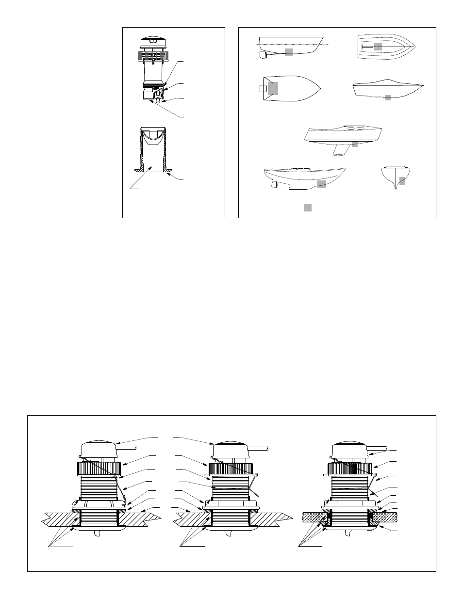
Paint the following surfaces
(see Figure 1):
• Outside wall of the insert below
the lower O-ring
• Paddlewheel cavity
• Paddlewheel
• Exposed end of the insert
• Exterior flange of the housing
• Bore of the housing up 30mm
(1-1/4")
• Blanking plug below the lower O-ring including the exposed end
Mounting Location
CAUTION: Do not mount in line with or near water intake or
discharge openings, or behind strakes, fittings, or hull
irregularities that will disturb the water flow.
CAUTION: Do not mount the sensor where the boat may be
supported during trailering, launching, hauling, or storage to avoid
damaging the transducer’s face.
• The water flowing under the hull must be smooth with a minimum of
bubbles and turbulence (especially at high speeds).
• The multisensor must be continuously immersed in water.
• The transducer beam must be unobstructed by the keel or propeller
shaft(s).
• Choose a location away from interference caused by power and
radiation sources such as: the propeller(s) and shaft(s), other
machinery, other echosounders, and other cables. The lower the noise
level, the higher the echosounder gain setting that can be used.
• Choose a location with a minimum deadrise angle, so the transducer
beam will be aimed at the bottom.
• Choose an accessible spot inside the vessel with adequate headroom
for the height of the housing, tightening the nuts, and removing the
insert. Allow a minimum of 280mm (11").
Boat Types
(see Figure 2)
• Displacement hull powerboats—Locate amidships near the
centerline. The starboard side of the hull where the propeller blades are
moving downward is preferred.
• Planing hull powerboats—Mount well aft, on or near the centerline,
and well inboard of the first set of lifting strakes to insure that the
multisensor will be in contact with the water at high speeds. The
starboard side of the hull where the propeller blades are moving
downward is preferred.
Outboard and I/O—Mount just forward of the engine(s).
Inboard—Mount well ahead of the propeller(s) and shaft(s).
Stepped hull—Mount just ahead of the first step.
Boat capable of speeds above 25kn (29MPH)—Review the
installation location and operating results of similar boats before
proceeding.
• Fin keel sailboats—Mount on or near the centerline and forward of the
fin keel 300–600mm (1–2').
• Full keel sailboats—Locate amidships and away from the keel at the
point of minimum deadrise.
2
planing hulls
Figure 2.
full keel sailboats
large displacement hulls
small displacement hulls
fin keel sailboats
Best location for multisensor
Copyright © 2005 Airmar Technology Corp
stepped hull
outboard and I/O
Figure 1. Anti-fouling paint
outside wall
paddlewheel
paddlewheel
bore of housing
exterior flange
O-ring
below lower
cavity
up 30mm (1-1/4")
of housing
insert
housing
exposed end
Copyright © 2006 Airmar Technology Corp
marine sealant on flange
Figure 3. Bedding and installing
cap nut
washer
hull
plastic housing
safety wire
housing
hull nut
insert
marine sealant on flange
stainless steel housing in metal hull
metal housing in non-metal hull
isolation
bushing
washer
and sidewall of housing
(plastic)
marine sealant on flange
cap nut
hull
safety wire
housing
insert
(plastic)
(metal)
hull nut
Copyright © 2005 - 2010 Airmar Technology Corp
(P617V shown)
(SS617V shown)
and sidewall of housing
and sidewall of housing
and isolation bushing where it contacts hull
BOW
►
(B617V shown)