Identify your model, Installation, Boat types – Airmar SS200—No Fairing User Manual
Page 2: Hole drilling, Bedding, Installing
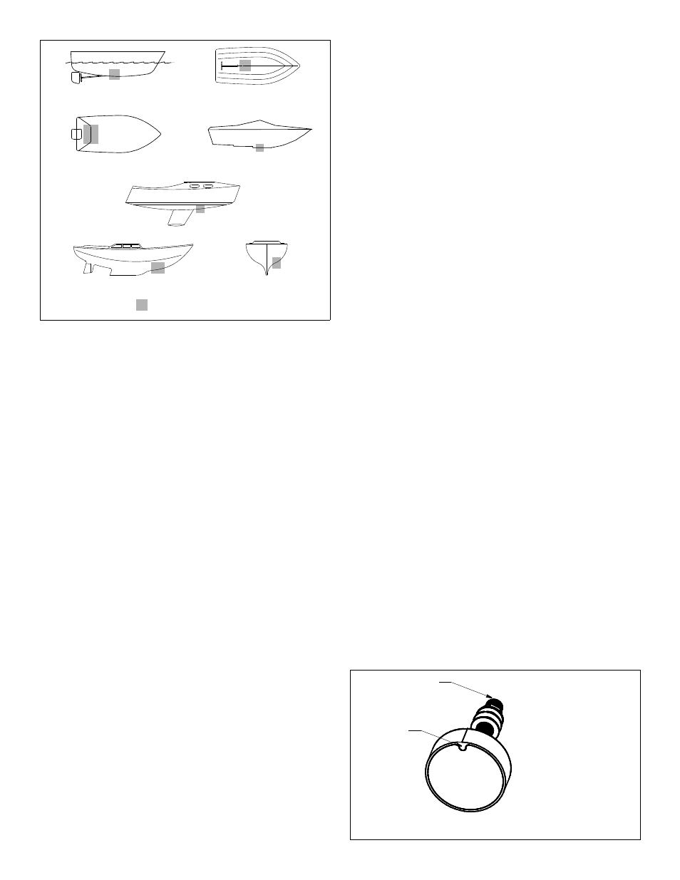
Boat Types
(see Figure 1)
• Displacement hull powerboat—Locate amidships near the
centerline. The starboard side of the hull where the propeller
blades are moving downward is preferred.
• Planing hull powerboat—Mount well aft near the centerline and
well inboard of the first set of lifting strakes to ensure that it is in
contact with the water at high speeds. The starboard side of the
hull where the propeller blades are moving downward is preferred.
Outboard and I/O—Mount just forward and to the side of the
engine(s).
Inboard—Mount well ahead of the propeller(s) and shaft(s).
Stepped hull—Mount just ahead of the first step.
Boat capable of speeds above 25kn (29MPH)—Review
transducer location and operating results of similar boats before
proceeding.
• Fin keel sailboat—Mount to the side of the centerline and
forward of the fin keel 300–600mm (1–2').
• Full keel sailboat—Locate amidships and away from the keel
at the point of minimum deadrise angle.
Identify Your Model
The model name is printed on the cable tag.
SS422—To aid orienting the transducer, use a permanent marker
to draw a mark on the stem in line with the mark on the face (see
Figure 2).
Installation
Hole Drilling
Cored fiberglass hull—Follow separate instructions on page 4.
1. Drill a 3mm or 1/8" pilot hole perpendicular to the waterline from
inside the hull (see Figure 3). If there is a rib, strut, or other hull
irregularity near the selected mounting location, drill from the outside.
2. Using the appropriate size drill bit or hole saw, cut a hole from
outside the hull. Be sure to hold the drill plumb, so the hole will
be perpendicular to the water surface.
3. Sand and clean the area around the hole, inside and outside, to
ensure the marine sealant will adhere properly to the hull. If there
is any petroleum residue inside the hull, remove it with either a mild
household detergent or a weak solvent (alcohol) before sanding.
Metal hull—Remove all burrs with a file and sandpaper.
2
planing hulls
Figure 1.
full keel sailboats
large displacement hulls
small displacement hulls
fin keel sailboats
Best location for transducer
Copyright © 2005 Airmar Technology Corp.
stepped hull
outboard and I/O
Figure 2. SS422 orientation
Copyright © 2013 Airmar Technology Corp.
mark
NOTE: Orient the mark on
the face and the mark you
have drawn on the stem
forward and parallel to the
centerline of the boat.
mark
Bedding
CAUTION: Be sure all surfaces to be bedded are clean and dry.
1. Remove the hull nut (see Figure 3).
2. Apply a 2mm (1/16") thick layer of marine sealant to the surface
of the transducer that will contact the hull /washer and up the
stem. The sealant must extend 6mm (1/4") higher than the
combined thickness of the washer, the hull, the second washer,
and the hull nut. This will ensure there is marine sealant in the
threads to seal the hull and hold the hull nut securely in place.
Metal hull—The stainless steel housing must be isolated from
the metal hull to prevent electrolytic corrosion. Use the isolation
sleeve and washers to separate the transducer stem from the
hull. However, the top of the isolation sleeve must be below the
hull nut after it is screwed into place, to prevent the sleeve from
interfering with tightening the nut. Slide the isolation sleeve over
the bedded transducer stem as far down as possible. Trim the
isolation sleeve to length. Apply a 2mm (1/16") thick layer of the
marine sealant to the outside of the isolation sleeve.
Installing
1. Slide a washer onto the cable and stem of the transducer. Rest
the washer against the transducer (see Figure 3).
2. From outside the hull, thread the cable through the mounting
hole. Then push the stem of the transducer through the hole
using a twisting motion to squeeze out excess sealant.
SS422—Orient the transducer, so the mark on the face and the
corresponding mark on the stem are forward and parallel to the
centerline of the boat (see Figure 2).
3. From inside the hull, slide the second washer and the hull nut
onto the cable. Rest the washer against the hull. Screw the hull
nut in place against the washer. Tighten the hull nut with slip-
joint pliers.
SS422—Be careful not to rotate the housing disturbing the
alignment. When grasping the stem, be careful not to damage
the threads.
Metal hull—Be sure the isolation sleeve is between the
transducer stem and the hull. However, the top of the isolation
sleeve must be below the hull nut to prevent the sleeve from
interfering with tightening the hull nut.
Cored fiberglass hull—Do not over-tighten, crushing the hull.
Wood hull—Allow for the wood to swell.
4. Remove any excess marine sealant on the outside of the hull to
ensure smooth water flow under the transducer.