Installation, Type of boat, Shortening the support tube – Airmar 1 kW—TM258 Long Bracket User Manual
Page 2: Assembling & positioning, Mounting
Type of Boat
•
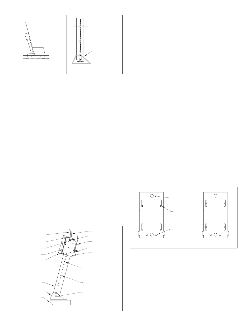
Single drive
—Mount a minimum of 15cm (6") beyond the
swing radius of the propeller (see Figure 1).
•
Twin drive
—Mount outside the drives a minimum of 15cm (6")
beyond the swing radius of the propeller.
•
Trim tabs
—Mount inside the trim tab, space permitting.
•
Drive extension
—Mount as far to the side as is practical.
•
Swim platform
—If the platform interferes with the movement of
the transducer, make a cutout to accommodate the transducer
and/or shorten the support tube.
•
Stepped transom
—Mount the transducer on the transom above
the step (see Figure 3). Use a straight edge to position the
underside of the transducer even with the underside of the transom.
Shortening the Support Tube
Caution
: The bracket must be able to release if the transducer is
struck by an object. Failure to release may cause damage to the hull.
Caution
: The upper latch pin must be inserted through the
TOPMOST holes of the support tube for the transducer to release.
Failure to pin the support tube through the TOPMOST holes can
result in damage to the bracket if it releases.
If the transducer assembly is too high for the selected mounting
location, the support tube
must
be shortened.
1. Remove the upper latch pin. Slide the support tube out of the
bracket (see Figure 4).
2. The support tube can be shortened in 25mm (1") increments up
to a maximum of 28cm (11"). Determine the amount to be
shortened from the
TOP
of the tube. Draw a line against the
bottom edge of the chosen hole
plumb
with the row of holes
(see Figure 5).
Do not cut the bottom of the support tube
.
Warning
: Always wear safety goggles and a dust mask.
3. Cut the
top
of the support tube to the desired length.
4. File and sand the cut edge to remove sharp edges and burrs.
5. Replace the support tube in the bracket (see Figure 4). Secure it
by sliding the upper latch pin through the
TOPMOST
adjustment
holes.
The upper latch pin must be inserted through the topmost
holes of the support tube for the transducer to release.
Installation
Caution
: Never pull, carry, or hold the transducer by the cable as
this may sever internal connections.
Assembling & Positioning
1. Thread the cable through the support tube (see Figure 4).
2. Using the 3 hex socket cap screws and a 3/8" wrench, attach
the transducer to the mounting shoe.
Do not tighten the center
screw at this time
. The transducer angle will be adjusted later.
3. With the transducer in the “down” position, hold the transducer
assembly at the selected location on the transom. Locate the
bottom of the transducer about 0–3mm (0–1/8") below the
bottom edge of the transom (see Figure 1).
4. Depending on the angle of your transom, the bracket may need a
shim(s) so the transducer clears the transom when it is raised and
lowered (see Figure 4). Check for clearances with the transducer
in the “up”, “down”, and “released” positions (see Figure 2).
Experiment with the shim(s) provided until there is sufficient
clearance while maintaining the transducer’s face parallel to the
water surface. (To help hold the shim(s) in place, bosses on the
shim(s) mate with the holes in the mounting plate.) When you are
satisfied with the mounting location, use a pencil to draw the
outline of the mounting plate on the transom (see Figure 6).
Note
: The bracket is factory preset to provide a vertical travel of
77mm (3") between the “up” and “down” positions. The vertical
travel can be adjusted by moving the LOWER latch pin to
another set of adjustment holes.
2
Figure 3. Stepped transom
hull
Figure 5. Shorten support tube
- immediately
below a hole
- plumb with the
row of holes
Do not cut bottom
(with small hole)
- cut top only
Figure 4. Assembly
upper latch pin
bracket
latch release line
latch lever
lower latch pin
transducer
hoist line
hinge pin
safety ring
mounting plate
support tube
mounting shoe
adjustment hole
cable
shim (2)
(17 pairs)
screw recess (2)
Figure 6. Mounting plate and screw locations
correct
incorrect
screw
reinforcement
bolt hole (2)
location (4)
Mounting
Caution
: The stainless steel bracket must be isolated from a
metal hull to prevent electrolytic corrosion. Use non-metal
insulating washers between the bracket and a metal hull.
1. Separate the mounting plate from the bracket by removing one
safety ring and withdrawing the hinge pin (see Figure 4).
2. Position the mounting plate on the transom over the pencil
outline with the shim(s) in place (see Figure 6).
Be sure
the
bracket is plumb with the waterline. (To hold the shim(s) in
place, mate the bosses on the shim(s) with the holes in the
mounting plate and tape them together.)
Copyright © 2005 Airmar Technology Corp.
Copyright © 2005 Airmar Technology Corp.
Copyright © 2005 Airmar Technology Corp.
Copyright © 2005 Airmar Technology Corp.
hole (2)
mates with
bosses on shim