Airmar 1 kW—TM258 Long Bracket User Manual
Page 3
Warning
: Always wear safety goggles and a dust mask.
3. Using a 4mm, #23 or 9/64" bit, drill four holes, 30mm (1-1/4")
deep, at the selected location. (To prevent drilling too deeply,
wrap masking tape around the bit 30mm (1-1/4") from the
point.)
Be sure
the drill is oriented parallel to the keel and at right
angles to the transom. Drill through any shim(s).
Do not drill the holes for the reinforcement bolts at this time.
Fiberglass hull
—Minimize surface cracking by running the drill
in reverse until the gelcoat is penetrated.
4. Apply marine sealant to the four #10 x 1-1/2" self-tapping
screws to prevent water seepage into the transom. Fasten the
mounting plate and any shim(s) to the hull with the screws
positioned at the bottom of each slot.
5. Attach the transducer assembly to the mounting plate with the
hinge pin and safety ring (see Figure 4).
6. Check again for clearances with the transducer in the “up,
“down”, and “released” positions.
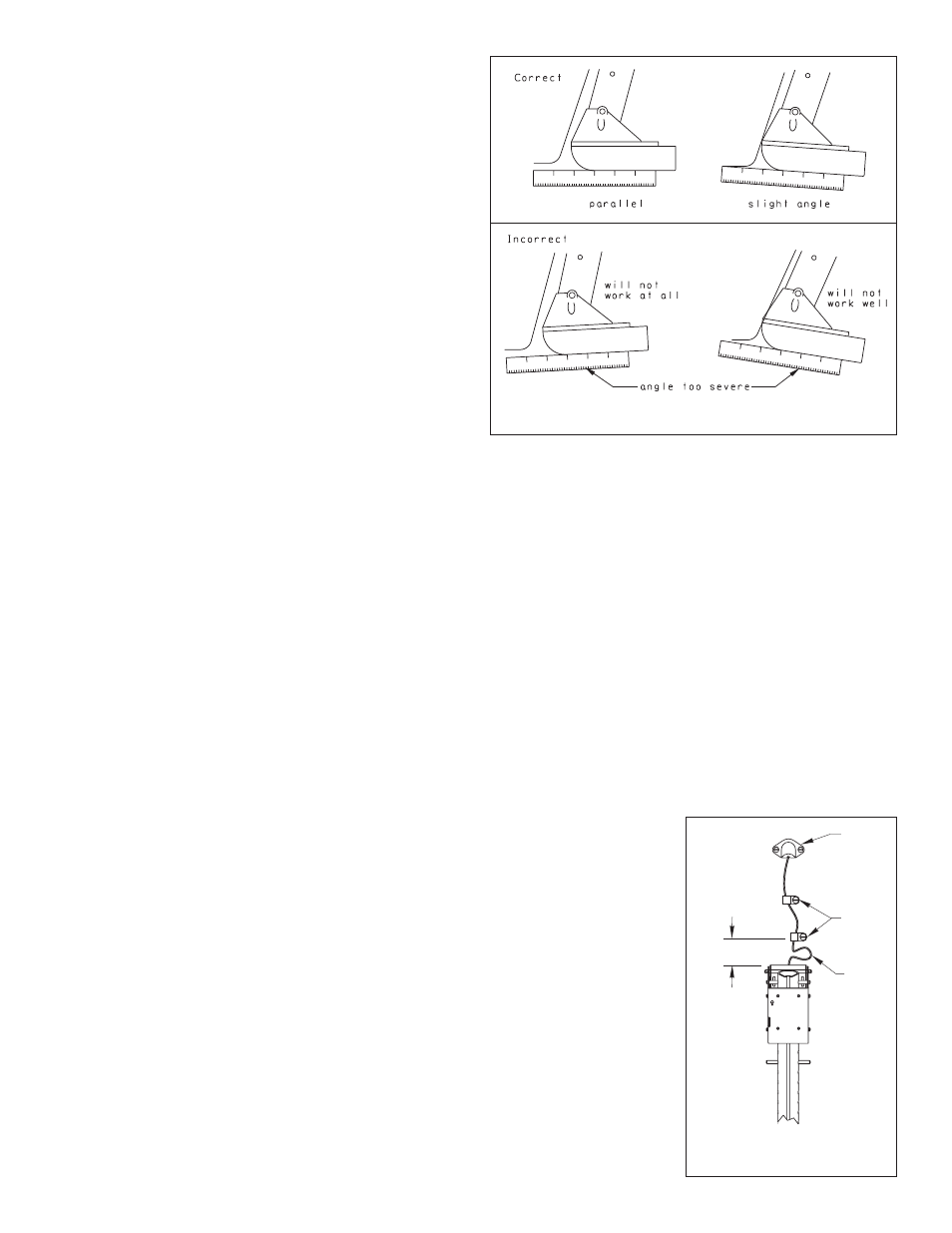
7. Using a straight edge, sight the underside of the transducer relative to
the underside of the hull (see Figure 7).
Being sure
the transducer’s
face is nearly parallel to the water surface, adjust the angle of the
mounting shoe to make the aft end of the transducer 3mm (1/8")
below the rounded forward end. Tighten the center screw.
8. The large diameter line is the hoist line. Tie it to the upper latch
pin
inside
the support tube with a boline knot. The small
diameter line is the latch line. Tie it to the latch lever with a
boline knot (see Figure 4).
You may want to hoist the transducer into the “up” position at
planing speeds [especially above 30kn (35MPH)]. To operate
the latch release line and the hoist line, it may be necessary to
devise a system of sheaves and eyes to a remote location.
Testing on the Water
1. Test the transducer at 200kHz with the engine off.
2. Become familiar with your echosounder’s performance at a
speed of 4kn (5 MPH).
3. Gradually increase the boat speed and observe the gradual
decline of performance due to turbulent water flowing over the
transducer’s active surface.
Note
: As the speed increases the performance at 50kHz will
deteriorate more rapidly because more acoustic noise is
generated at low frequencies.
4. If the decline in performance is sudden (not gradual), identify
the boat speed at which the onset occurred. Return the boat to
this speed, then gradually increase speed while making
moderate turns in both directions.
5. If the performance improves while turning to the side on which
the transducer is installed, it’s position probably needs
adjustment. The transducer is probably in turbulent or aerated
water. Move the transducer farther down into the water in
increments of 12mm (1/2"). If the performance does not
improve satisfactorily, move the transducer closer to the
centerline (keel). Fill unused screw holes with marine sealant.
Bolting the Assembly
When you are satisfied that the mounting location provides good
performance, reinforce the mounting bracket with bolts, washers,
and nuts (not supplied). Since transom thicknesses vary and most
installations require a shim(s), the installer must determine the
appropriate length bolt.
1. Separate the bracket from the mounting plate by removing one
safety ring and withdrawing the hinge pin (see Figure 4).
Warning
: Always wear safety goggles and a dust mask.
2. Drill the two reinforcement bolt holes through the hull and any
shim(s) (see Figure 6).
3. Apply sealant to the bolt threads to prevent water seeping into
the transom. Tap the bolts into place. Apply the washers and
nuts inside the transom.
4. Reattach the bracket to the mounting plate with the hinge pin
and safety ring.
Cable Routing
Route the cable over the transom for a detachable installation. For
permanent mounting, route the cable through a drain hole or
through a new hole drilled in the transom
above the
waterline
.
Caution
: Never cut the cable or remove the connector; this will
void the transducer warranty.
Warning
: Always wear safety goggles and a dust mask.
1. If a hole must be drilled through the transom,
choose a location
well above the waterline
(see Figure 8). Check for obstructions
such as trim tabs, pumps, or wiring inside the hull. Mark the
location with a pencil. Drill the hole using the appropriate size bit
to
accommodate the connector.
2. Route the cable over
or
through the transom.
3. On the outside of the hull,
secure the cable against
the transom using the cable
clamps. Position one cable
clamp 15cm (6") above the
bracket. Mark the mounting
hole with a pencil.
4. Position the second cable
clamp halfway between the
first clamp and the cable
hole. Mark this mounting
hole.
5. If a hole has been drilled
through the transom, open
the large slot in the transom
cable cover. Position the
cover over the cable where
it enters the hull. Mark the
two mounting holes.
6. At each of the marked
locations, use a 3mm or
1/8" bit to drill a hole 10mm
3
Figure 7. Transducer angle
Figure 8. Cable routing
cable
clamps
cable
cover
15cm (6")
4" of
slack
10cm
Copyright © 2005 Airmar Technology Corp.
Copyright © 2005 Airmar Technology Corp.