Pit cart chassis kit c construction and assembly – Allstar Performance ALL10600 User Manual
Page 2
Allstar Performance 8300 Lane Dr., Watervliet, MI 49098
Phone: (269) 463-8000 Fax: (800) 772-2618 www.allstarperformance.com
Form 1132
Page 2 of 2
Rev. 031014
Pit Cart Chassis Kit
C
Construction And Assembly
Chassis Assembly:
1.
Install king pin bushings into spindles and apply a light coat of grease to the inside, top and
bottom of bushings.
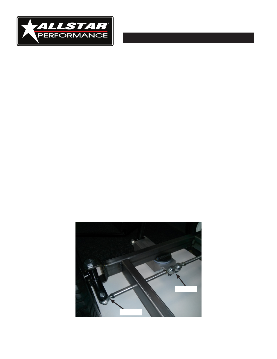
2.
Install spindles to frame with the 5/8"-11 x 4" bolts and locking nuts, tighten until slight drag is felt
when moving the spindle back and forth. Note: Steering arms should be located towards the back
and below the axle centerline, see Figure #1.
3.
Install steering block spacer, steering block and lock nut as shown in Figure #2. Apply a small
amount of grease to steering plate spacer and tighten locknut until slight drag is felt when moving
steering block back and forth.
4.
Assemble tie rod assemblies by first installing the correct thin jam nut onto each rod end and then
completely install rod ends into threaded tubes, be aware there are LH and RH rod ends.
5.
Install tie rod assemblies as shown using the four 3/8"-16 x 1-1/2" bolts and lock nuts. Set steering
toe-in-out by adjusting threaded sleeves, once correct toe is set tighten locking nuts. Note: It may be
necessary to install 3/8" washers between spindle arms and tie rod ends as spacers to clear side rails
of cart, only 1/8" - 1/4" of clearance is needed when steering is moved from side to side.
6.
Install handle into steering block and fasten handle in place with 1/2"-13 x 3-1/2" handle bolt and
1/2"-13 lock nut. Handle should curve out away from cart when properly installed.
7.
Install grip by sliding over the open end of handle.
8.
A handle retaining clip and rivets are included to secure handle to a finished box.
9.
Install 3/4" I.D. x 7/8" long wheel spacers on front spindles.
10.
Install wheel and tire assemblies with valve stems facing out and retain with four 3/4"-10 lock nuts.
Figure #1
Figure #2