Assembly instructions race car lift – Allstar Performance ALL11272 User Manual
Page 2
Allstar Performance 8300 Lane Dr., Watervliet, MI 49098
Phone: (269) 463-8000 Fax: (800) 772-2618 www.allstarperformance.com
Form 1125
Page 2 of 2
Rev. 022613
Allstar Performance® will not assume liability for personal or property damage resulting from the use or misuse of any
product we manufacture or sell, whether on the street or on the race track. Purchase and/or use of this product implies
recognition and acceptance of our entire warranty and disclaimer by customer.
SAFETY STOPS
WARNING - USE BOTH SAFETY STOPS AT ALL TIMES WHEN CAR
LIFT IS RAISED. FAILURE TO USE SAFETY STOPS MAY RESULT IN
PERSONAL INJURY OR PROPERTY DAMAGE.
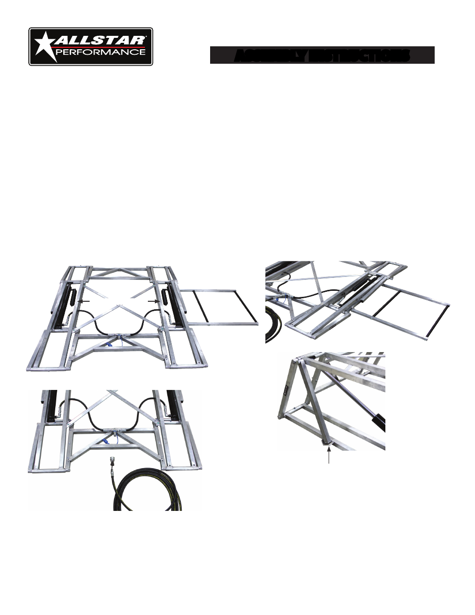
1. Remove contents from all cartons and place on a flat level surface.
2. Place lift platform assemblies (A & B) in a parallel position so that the Allstar logos are facing out and the hydraulic cylinders
are facing in the same direction as shown in Image 1.
3. Locate the two bridge assemblies (C & D). Position bridge assembly (C) with hydraulic hoses at the end of lift platform as-
semblies (A & B) closest to base of hydraulic cylinders as shown in Image 2. Position the remaining bridge assembly (D) in the
same direction as bridge assembly (C) as shown in Image 1.
4. Secure both bridge assemblies using supplied 1/4" x 1-3/4" bolts (install bolts from the bottom, face threads up), lock washers
and nuts. It will be necessary to raise the lift manually approximately 2" and place a stop (such as small length of 2x4 lumber)
between the upper and lower rails to install two of the bridge assembly fasteners.
5. Route hoses under bridge and platform rails. Connect hoses to hydraulic cylinders as shown in Image 2.
6. Install "X" brace as shown in Image 1.
7. Install supplied female quick disconnect to end of hose using thread sealant and attach to male fitting on lift.
8. Carefully remove stop supporting lift from step 4.
9. Inflate down assist canisters to 100 PSI with the lift in a fully lowered position.
10. Assemble the handle sides (E) to handle support tubes (F) using (4) 3/8" x 1/2" bolts. Attach assembled handle to the lift with
1/4" x 3/4" bolts as shown in Image 3.
11. To prevent damage during shipping, grease fittings are shipped uninstalled. Install fittings in all applicable holes and apply
grease sparingly.
12. Two optional riser blocks (G) are included to install on the lift as needed.
Image 1
Image 2
Image 3
ASSEMBLY INSTRUCTIONS
Race Car Lift
Inflate to 100 PSI