Allstar Performance ALL81222 User Manual
Contents list, Gm distributor instructions
Allstar Performance 8300 Lane Drive, Watervliet MI 49098
Phone: (269) 463-8000 Fax: (800) 772-2618 www.allstarperformance.com
FORM 1032
Page 1 of 4
Rev.053013
Contents List:
(1)
Fully machined 6061-T6 aluminum distributor with vacuum advance
(1)
Pre-installed rotor
(1)
Pre-installed cap
(1)
Plug wire retainer with two self tapping screws
(1)
Gasket
(1)
Lock out kit for vacuum advance
(1)
Three-pin wire harness
(2)
O-rings, for use with modified engine block
(4)
Advance stop bushings, blue pre-installed
Red = 28 crankshaft degrees Silver = 25 crankshaft degrees
Blue = 21 crank shaft degrees Black = 18 crankshaft degrees
(3 pr) Advance springs, blue pre-installed
1 pair blue – normal rate of advance
1 pair dark silver (small spring coil) – faster rate of advance
1 pair light silver (large spring coil) – slower rate of advance
(1 pr) Replacement allen-head screws
Distributor Removal/Installation
1. Remove the existing distributor cap, but do not disconnect any spark plug wires.
2. Use a remote start switch or have a helper crank engine until the rotor is pointed at the #1 cylinder.
3. Disconnect the battery cables, remove the NEGATIVE (-) cable first.
4. Reinstall the distributor cap briefly to check that the rotor and the #1 spark plug wire are in line. Once noted, mark for refer-
ence, remove cap and lay to the side. If necessary, mark spark plug wires and remove them from the distributor cap.
5. Disconnect all other wires to distributor, noting where they were attached.
6. Loosen the distributor hold down clamp and rotate the clamp to the side or remove. Lift distributor straight up to remove
from the engine. (The spiral cut gear will cause the rotor to rotate as the distributor is pulled out of the engine. Be sure to com-
pensate for the spiral gear shape when installing the new distributor.)
7. Remove old gasket and clean surface to prepare for new gasket.
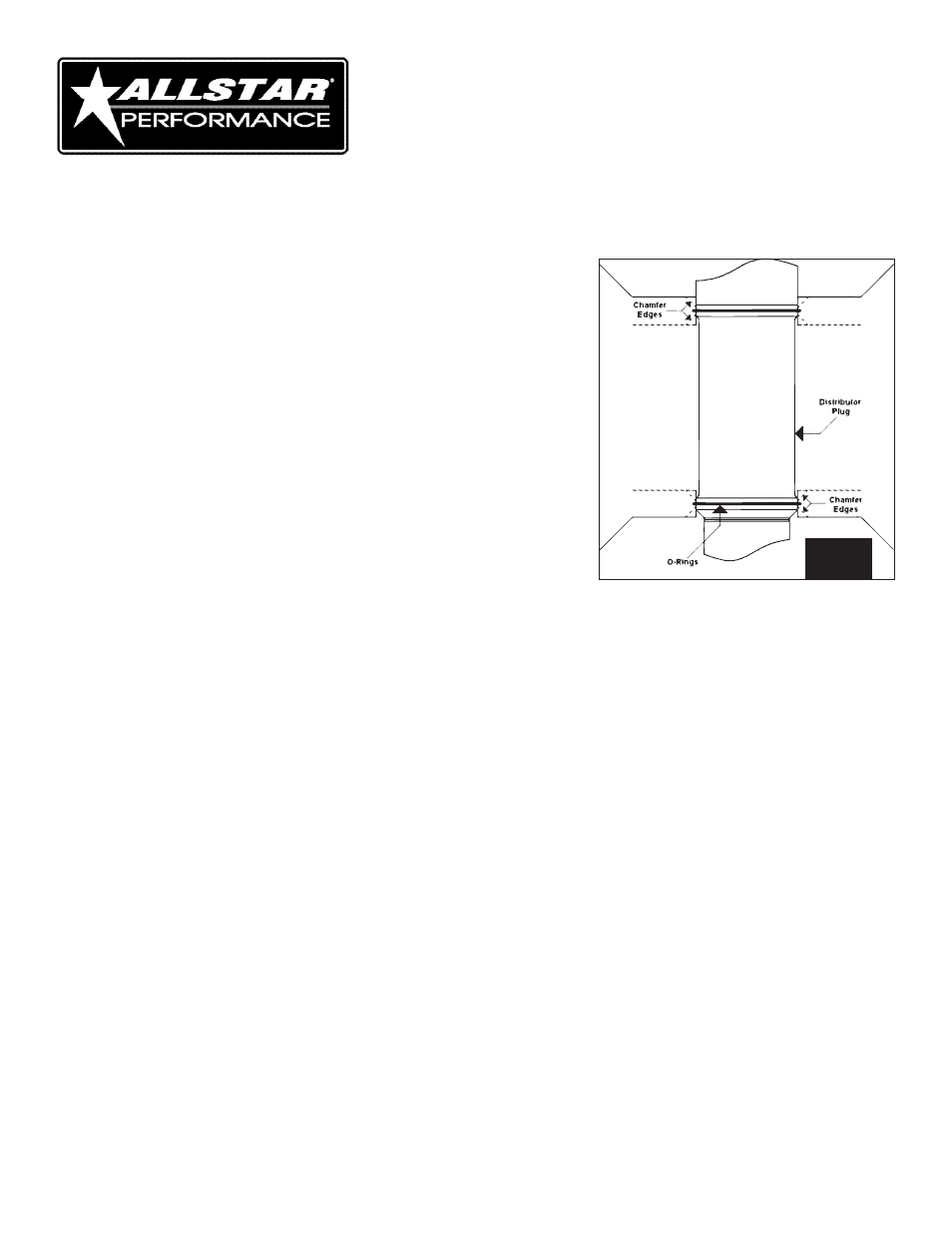
8. Install O-rings if engine block has been modified. See figure 1.
9. Install the gasket between distributor and intake manifold.
10. Apply a liberal amount of zinc or moly grease to the distributor gear to ensure proper gear break-in. (Grease sold separately.)
If the distributor does not drop into place and fully seat against the intake manifold, remove the distributor and, using a long,
standard screwdriver, rotate the oil pump shaft with a long screwdriver until the shaft lines up with the distributor drive. Make
sure distributor is fully seated after this adjustment (there should not be any gap between distributor housing, gasket and
intake manifold).
FIG. 1
GM Distributor Instructions
Please read all instructions BEFORE installation
The drive gear installed on this distributor is melonized and is compatible with flat tappet or hydraulic roller camshafts. If used
with a mechanical roller camshaft, a bronze or other compatible gear (sold separately) for 0.500" shaft should be used.