Locking out vacuum advance, Break-in period required, Limited warranty – Allstar Performance ALL81222 User Manual
Page 4
Allstar Performance 8300 Lane Drive, Watervliet MI 49098
Phone: (269) 463-8000 Fax: (800) 772-2618 www.allstarperformance.com
Locking Out Vacuum Advance
1. If you have decided to use the vacuum advance, this modification is
most easily accomplished before distributor installation.
2. Remove roll-pin from the drive gear and remove the gear and
thrust washer from shaft.
3. Remove shaft from housing.
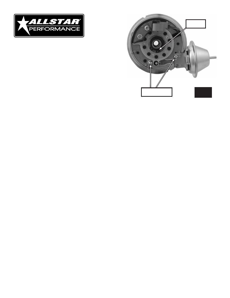
4. First remove the two Allen head screws that secure the advance
canister to the distributor. See Figure 5.
5. Using a pair of snap ring pliers, remove the snap ring that holds the
magnetic pickup plate in place. See Figure 5.
6. Lift up on the magnetic pickup to complete vacuum canister re-
moval.
7. Next secure the lock out plate onto the distributor housing using
the previously removed Allen head screws. At this point, only slightly tighten.
8. Install one of the supplied machine screws with washer though the lockout and tighten.
9. If the pickup plate is installed incorrectly, be cautioned that the reluctor paddles could come into contact with the pickup. Be
sure to install the pickup plate parallel with the distributor housing and always check for proper clearance by inserting shaft as-
sembly and rotating distributor shaft. If contact between the reluctor paddles and pickup is observed, use one of the included
shims between the lockout plate and distributor housing to compensate. If no shims are needed between the lockout plate
and distributor housing, use one beneath the washer of machine screw which holds down the lockout plate.
10. Once you’ve confirmed that the reluctor paddles do not come into contact with the pickup, fully tighten the Allen head
screws, remove shaft assembly and reinstall the snap ring.
11. Install shaft assembly back into housing, install thrust washer, gear and roll pin.
Note: Be sure to recheck your timing and plug any existing vacuum ports.
Break-In Period Required
• Prior to completion of the installation, the distributor gear should have received a coating of zinc or moly based grease (grease
sold separately). It is the responsibility of the installer to apply this grease.
• Do not use synthetic oil during break-in period. Once break-in period is complete, any suitable oil may be used.
• On modified engines with oil pressure above 70 psi (cold), the gear should be broken-in with racing grade mineral oil.
• Monitor gear wear after several hours of break-in. Check the gear for proper mesh, alignment, and wear.
Limited Warranty
Manufacturer’s obligation for warranty returns shall be limited to repairing, replacing, or crediting as its option, any parts found
to be defective. Manufacturer will not be liable for charges and/or other expenses incurred, nor shall it be liable for damages or
injury to persons or property resulting from the misuse or improper installation of any part subject to this warranty. The warranty
contained herein is expressly in lieu of any and all other warranties, including any implied warranty of merchantability or fitness
for any particular purpose.
FORM 1032
Page 4 of 4
Rev.053013
FIG. 5
Allen Head Screws
Snap Ring