Aquatic AV AQ-AC520 User Manual
Page 3
DESCRIPTION
The Aquatic AV AQ-AC520 4-channel marine amplifier is an excellent choice
for creating a variety of multi-channel sound systems. It features built-in
system design flexibility that allows you to create a 2, 3 or 4 channel amplifier
with a flip of a switch. You can also configure the front or rear amplifier
sections for a mixed mode operation to drive a set of satellite speakers and/or
subwoofer.
The built-in 12dB per octave electronic crossover lets you custom tailor the
sound of the front and rear channels, using two independent filters with
adjustable crossover frequencies for high-pass or low-pass filtering.
The amplifier also uses an unregulated MOSFET power supply for superior
control of output wattage. A toroid-coil transformer yields maximum power
transfer with minimum heat loss. Careful circuit design keeps AM RFI at low
levels, so you won’t hear unwanted noise when the level is cranked up.
Protection circuits safeguard the amplifier against overheating, speaker shorts,
or improper load conditions that may occur.
All connections and controls are on the end panels and are easy to understand.
We use gold-plated RCA and barrier connectors to ensure the best electrical
connection for your system. Included are external automotive type fuses that
are easy to replace.
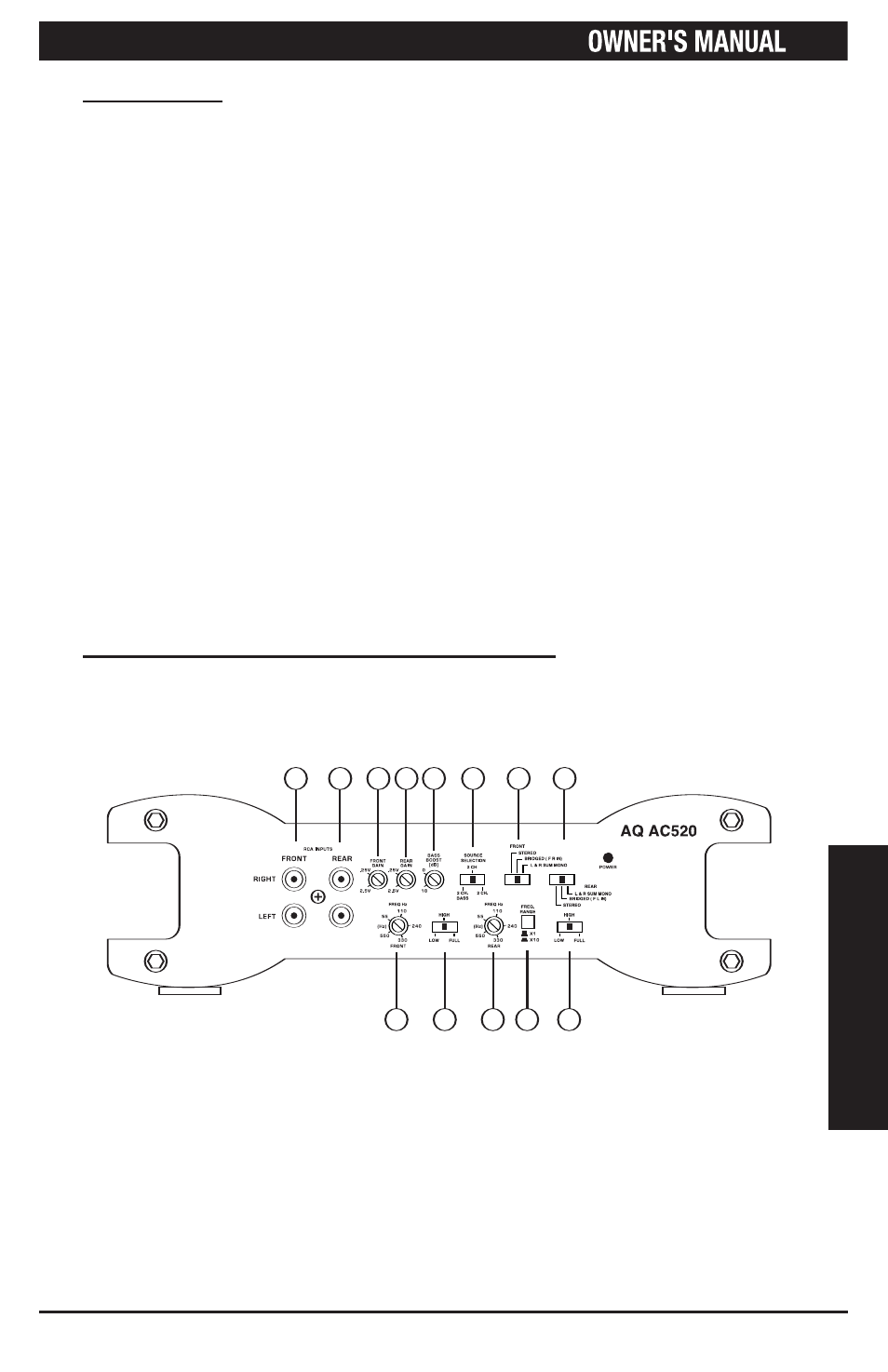
INPUT CONNECTIONS AND AUDIO CONTROL
The front panel of the Aquatic AV AQ-AC520 contains connections for RCA
Inputs and Audio Control as shown below.
1
D
E
S
C
R
IP
T
IO
N
12
3
4
5
6
7
8
9
10
11
12
13
1. Front RCA Input Jacks
2. Rear RCA Input Jacks
3. Front Gain Control
4. Rear Gain Control
5. Bass Boost Control
6. Source Selection Switch
7. Front Input Mode Switch
8. Rear Input Mode Switch
9. Front Frequency Control
10. Front X-Over Mode Switch
11. Rear Frequency Control
12. Multiplier Switch
13. Rear X-Over Mode Switch
Figure 1-