Grass Valley 2020ADC A-To-D User Manual
Page 15
2020ADC — Instruction Manual
15
Power Up
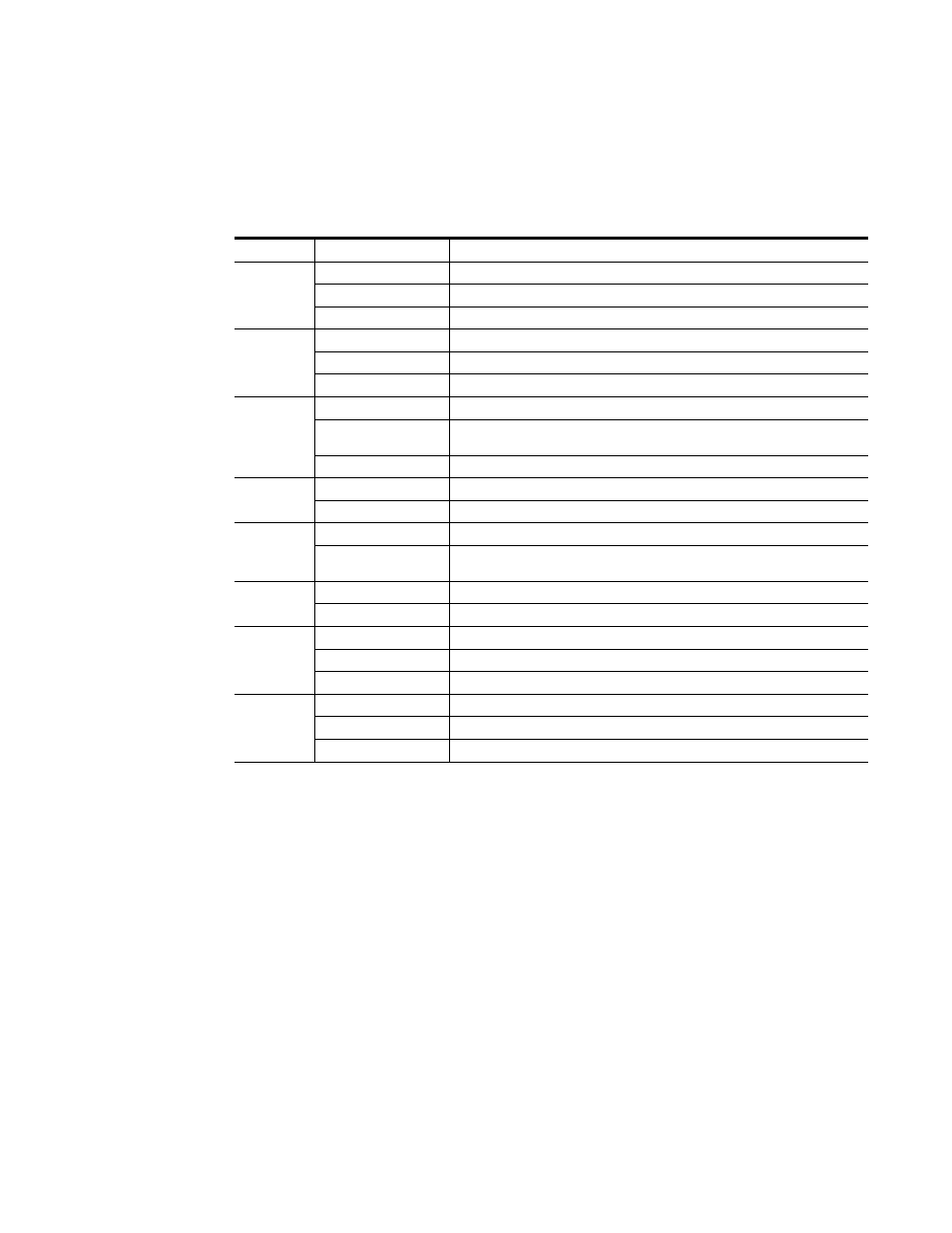
A red FAULT LED indicates an error situation and, with the other LEDs,
can indicate the operational conditions presented in
. The table
describes signal output and LED indications for various input/reference
combinations and user settings.
Table 3. Indicator LEDs and Conditions Indicated
LED
Indication
Condition
FAULT
(red)
Off
Normal operation.
On continuously
Module has detected an internal fault.
Flashing
Reference input is faulty or not present.
COMM
(yellow)
Off
No activity on frame communication bus.
Long flash
Location Command received by the module from a remote control system.
Short flash
Activity present on the frame communication bus.
CONF
(yellow)
Off
Module is in normal operating mode.
On continuously
Module is initializing, changing operating modes or updating firmware. Simultaneous
CONF and FAULT LEDs on indicate FPGA load error.
Flashing
Indicates rate of change of paddle-controlled analog setting.
PWR
(green)
Off
No power to module or module’s DC/DC converter failed.
On continuously
Normal operation, module is powered.
REM OVER
(yellow)
Off Module
configuration
matches switch and jumper settings.
On continuously
Module configuration may not match switch and jumper settings. Control has been
remotely overridden.
LOCK
(green)
Off
Module does not detect a valid AES in reference signal.
On continuously
Valid AES in reference signal is present and module is locked to it.
20 dB
CH1-4
(green)
Off
Channel level is less than -20 dBFS.
On continuously
Channel level is greater than -20 dBFS.
Flashing
Channel level is transitioning through -20 dBFS
CLIP
CH1-4
(red)
Off
Channel digitized signal level is less than -0.5 dBFS.
On continuously
Channel digitized signal level is greater than -0.5 dBFS.
Flashing
Channel digitized signal level is transitioning through -0.5 dBFS.