Grass Valley 8943FC User Manual
Page 21
8943FC — Instruction Manual
21
Installation
6.
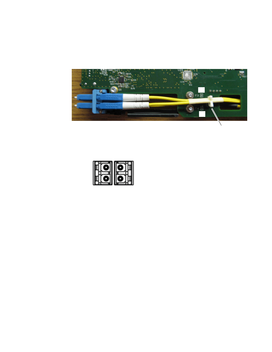
Insert the simplex ends of the fiber cable assembly (the two fiber optic
connectors are separate) into the LC adapter ports at the rear of the
module (shown in
). Fiber Channel 4 (A) is the bottom cable
from the SFP device and Fiber Channel 3 (B) is the top cable.
Figure 14. F3 and F4 Fiber Cabling on Back of Circuit Board
The fiber optic inputs from the rear module are shown in
Figure 15. Fiber Optic Outputs
For the SFP device types and cabling examples used in this 8943CF/FC
manual set, the following frequencies should be input from this connector:
•
Fiber In 1 = 1610nm
•
Fiber In 2 = 1590nm
•
Fiber In 3 = 1570nm
•
Fiber In 4 = 1550nm
If you are using 8943FCs to multiplex 8 or 16 frequencies through the
8939FCA/FCB modules, the other 8943FCs should be equipped with the
SFP devices as described in
CWDM 16 Channel Configuration on page 28
.
Fiber 4
Fiber 3
Cable guide
B
A
IN
IN
1
2
3
4