Grass Valley 8943FC User Manual
Page 30
30
8943FC — Instruction Manual
Installation
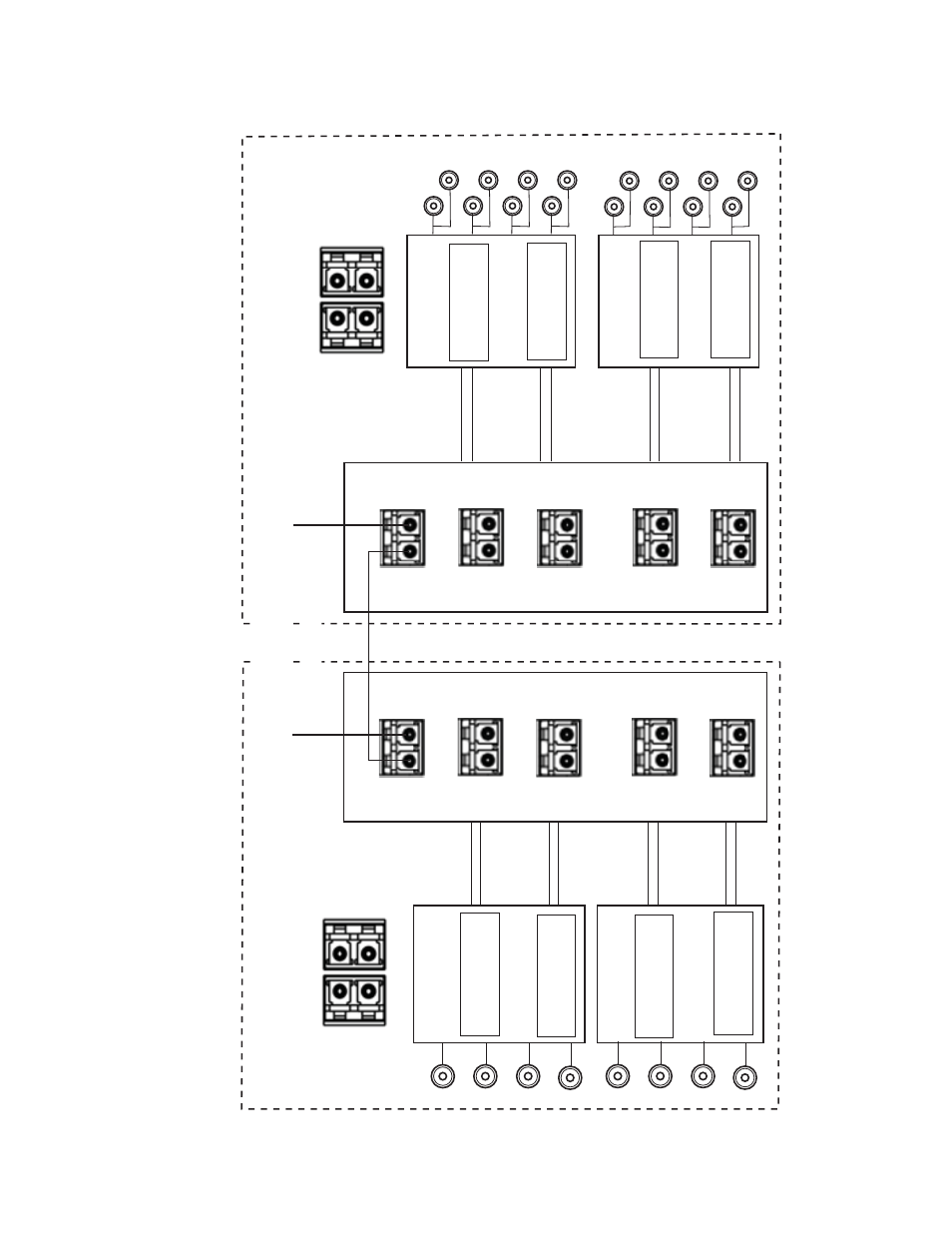
Figure 24. 8939FCB Configuration – Channels 9 -16
8772_05r1
8939FCA
8943CF
Fiber Out 1
to 1450nm
Fiber In 1
from 1450nm
Fiber In 2
from 1430nm
Fiber In 3
from 1410nm
Fiber In 4
from 1390nm
Fiber Out 3
to 1410nm
Fiber Out 4
to 1390nm
Fiber Out 2
to 1430nm
Fiber Out 1
to 1370nm
Fiber Out 3
to 1330nm
Fiber Out 4
to 1310nm
Fiber Out 2
to 1350nm
Electrical
Inputs
To
8939FCA
DEMUX COM port
To
8939FCA
MUX COM port
Multiplexer
Demultiplexer
Connector J6
Connector J4
8943CF
SFP-CWDM3G-7-K
1390nm & 1410nm
Fiber In 1
from 1370nm
Fiber In 2
from 1350nm
Fiber In 3
from 1330nm
Fiber In 4
from 1310nm
Connector J6
SFP-CWDM3G-8-K
1430nm & 1450nm
Connector J4
SFP-CWDM3G-5-K
1310nm & 1330nm
SFP-CWDM3G-6-K
1350nm & 1370nm
8943FC
Connector J6
Connector J4
Connector J6
SFP-1310-M1DRX-K
1270 > 1610nm
SFP-1310-M1DRX-K
1270 > 1610nm
SFP-1310-M1DRX-K
1270 > 1610nm
SFP-1310-M1DRX-K
1270 > 1610nm
Connector J4
COM
EXP
CH9
1310nm
CH10
1330nm
CH12
1370nm
CH11
1350nm
CH14
1410nm
CH13
1390nm
CH16
1450nm
CH15
1430nm
8939FCA
COM
EXP
CH9
1310nm
CH10
1330nm
CH12
1370nm
CH11
1350nm
CH14
1410nm
CH13
1390nm
CH16
1450nm
CH15
1430nm
8943FC
Electrical
Outputs
Location A
Location B
8943FC Fiber Inputs
1
2
4
3
IN
IN
8943CF Fiber Outputs
1
2
4
3
OUT
OUT
Ch 1
Ch 2
Ch 3
Ch 4
Ch 1
Ch 2
Ch 3
Ch 4
Ch 1
Ch 3
Ch 4
Ch 2
Ch 1
Ch 2
Ch 3
Ch 4
Ch 1
Ch 3
Ch 4
Ch 2
Ch 1
Ch 2
Ch 3
Ch 4
Note: In any configuration utilizing CWDM transmitters, if the distance between 8939FCA modules is less than 12 km (7.5 m
),
a 3 dB attenuator must be installed somewhere between the COM ports on the 8939CF
A modules to prevent overdriving the receiver
causing bit errors
to occur on the link.
*
Single-mode fiber cable
*
Distance of
up to 50km