Power up, Operation indicator leds – Grass Valley 8949MDA-CFR v.1.0.X User Manual
Page 16
16
8949MDA-CFR and 8949MDA-SFR Instruction Manual
Power Up
Power Up
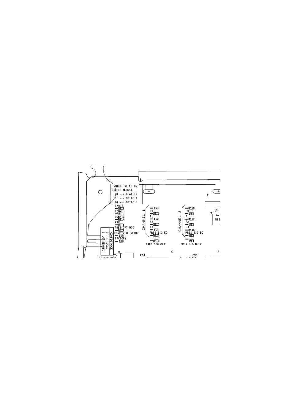
The on-board LED indicators are illustrated in
. Upon power-up, the green
PWR LED should light and the CONFIG, FAULT and COMM LEDs should illu-
minate during the module initialization.
Note
When a module is first plugged into a GeckoFlex frame, the 8900NET module
(if present) may report a momentary fault. This will clear once the module has
booted up.
Operation Indicator LEDs
With a valid input signal connected, PRES SIG LED (EQ in channel 1, OPT1,
OPT2) should be on. Refer to
to see a complete list of possible
operating conditions and the resulting indicator status.
Figure 7. LEDs Significations - Part of the 8949MDA-CFR or 8949MDA-SFR module
Note
The channel 2 LEDs are not connected.