Web page operations and functional elements – Grass Valley 8977AP-4B User Manual
Page 24
24
8977AP-4B/4U — Instruction Manual
Remote Configuration
Web Page Operations and Functional Elements
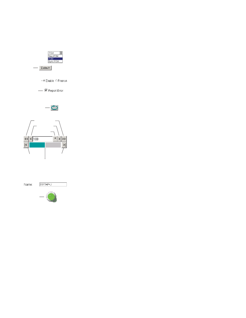
The following conventions and functional elements (shown at left) are used
in GeckoFlex web page operations. (The examples shown throughout this
manual represent 8900NET software version 4.0.2 or later):
•
Pulldown menus allow you to choose selections from a list.
•
Clicking on a button performs an immediate action such as recall of
defaults, clearing of states, learning configurations, and selecting all or
none of a selection.
•
Radio buttons are used to make a choice of one parameter in a group.
•
Check boxes are used when a selection can be enabled or included in a
group. Multiple check box selections or enables can be made for some
parameters.
•
A
Refresh
button (circular arrow) is provided at the top of each web page
for manual refresh to view recently changed parameters.
•
Each numerical adjustment control has a
Coarse
adjust button (left and
right top double arrows) which increases or decreases the step value by
a factor of 10. The
Fine
adjust button (left and right inside single arrows)
increases or decreases the step value by 1.
To change a value, use the arrow button controls or enter a value into
the number field and select the
Enter
button (
*
) or use the
Enter
key on
your keyboard. The Status Indicator bar will follow the value selected.
Use the
Low
and
High
Limit
buttons to go directly to the lowest and
highest limits for the parameter.
•
An entry field allows naming of various module functions such as
input or output signals, asset tag, and slot identification.
•
The
Status
LED icon reports communication status for the frame slot and
is a link to the module Status web page where Warnings and Faults are
displayed.
LED colors indicate:
•
Green = Pass – no problems detected.
•
Yellow = Configuration error warning (presence of one warning),
configuration mismatched or input missing.
•
Red = Fault condition detected (presence of one alarm).
•
Graphic and arrow colors used indicate the following:
•
Green = Pass – signal or reference present, no problems detected.
•
Red = Fault – fault condition.
•
Yellow = Warning – signal is absent or has errors.
•
Gray = Not monitored.
•
White = Empty or not present.
Pulldown Menus
Check box
Refresh button
Coarse Adjust
Fine Adjust
Enter
Status LED
Entry Field
High Limit
Status Indicator
Low Limit
Radio button
Button