Mounting the cameraman 3-ccd digital camera, Page 8 – Grass Valley 3-CCD CameraMan Rev A User Manual
Page 11
Page 8
CameraMan® 3-CCD DIGITAL Camera Installation and Operations Manual
Mounting the CameraMan 3-CCD DIGITAL Camera
Mount the DIGITAL Camera on any flat, non-slick, non-metal surface with a minimum
supporting area of 8”x8” by following these easy steps.
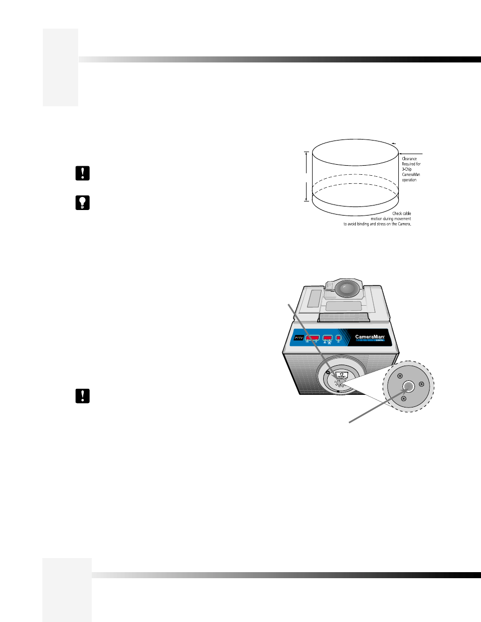
Zero degree
position
mark
1/4”-20 UNC Mounting
Screw Hole
Step 1: Check the selected camera-location to ensure that there is enough
camera and cable clearance space (right) for the CameraMan to pan
and tilt without obstruction.
Note: Do not mount the camera upside down, or with more
than a 10° angle from horizontal.
Tip: See Appendix E: FIELD OF VIEW SPECIFICATIONS
on page 18, to assist in placing the CameraMan to achieve
optimum optical views.
Step 2: Locate the zero-degree position mark labeled FRONT on the bottom
of the base unit. This mark helps ensure that the base unit is
calibrated correctly. Point this indicator mark in the direction that best
reflects the center of travel in which the camera will be used (usually
the center of the room).
Step 3: To ensure that the camera-mounting is not prone to vibrations,
securely fasten the camera to a rigid flat surface using a 1/4"-20
UNC cap screw that does not extend into the base platform by more
than 0.4". (The screw hole is provided in the base platform for
this purpose. The cap screw is not provided.) This screw should
be hand-tightened. If necessary, use a non-hardening threadlock to
prevent the screw from loosening.
Note: Be sure to take environmental conditions into
consideration when operating the camera. Always operate
the camera indoors, and follow the temperature and
humidity specifications outlined in Appendix C: CAMERA
SPECIFICATIONS on page 16.
Diameter
30.0"
17.0"