Rack-mount installation, Frame and electrical installation, Frame – Grass Valley Kaleido-X (7RU) v.7.70 User Manual
Page 17
5
Kaleido-X (7RU)
Hardware Description & Installation Manual
• Mouse
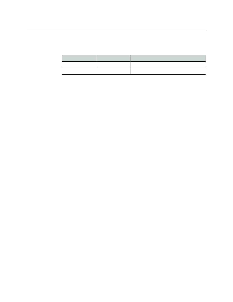
• Serial port adapters (one with straight cabling and one with crossover cabling for each
output card in your multiviewer):
Rack-Mount Installation
A Kaleido-X multiviewer may be installed in a standard 19-inch rack, using the proper
screws and washers (not included). The Kaleido-RCP2 Remote Control Panel (optional) may
also be installed in a rack using the optional KRCP-RK2 mounting kit.
For proper ventilation, make sure the front and side panel air vents are not blocked and the
air filter is clean.
Frame and Electrical Installation
Kaleido-X (7RU) is a self-contained unit consisting of a frame, redundant power supplies,
and various input and output cards. The monitor wall displays and external control devices
complete the system.
Frame
The Kaleido-X (7RU) frame is 7 RU high. It incorporates an internal midplane for
interconnecting the cards. Cards are installed from the front of the frame. Each card is
associated with input and/or output connectors which are mounted on a connector panel.
These connector panels are installed from the rear of the frame, in the same horizontal
position as their associated card. The redundant power supplies are installed at the top of
the frame.
The hinged front door can be opened to give access to the cards. A removable retaining bar
across the front of the frame inside the door holds the cards securely in place.
The Kaleido-X (7RU) frame incorporates the following key elements:
• A rack-mountable mechanical framework
• A side-opening, removable door to cover and protect the front of the frame and the
installed cards
• A midplane board that enables inter-card communication
• Slots for installing signal processing cards that plug into the midplane
• Mounting points for rear connector panels
• Redundant power supplies
• Ventilation
The front slots and rear panel connection points are color-coded according to the type of
card that can be located in the slot. The extractor handles on the cards are color-coded to
Part number
Adapter cabling
RS-422 pinout at the DE-9P connector
1737-3000-102
Straight
Controller (SMPTE master) mode
1792-3700-100
Crossover
Tributary (SMPTE slave) mode