Grass Valley K-Frame Installation Planning Guide Jul 07 2014 User Manual
Page 45
K-FRAME — Installation Planning Guide
45
Video Processor Frame GPI/Tally Interface
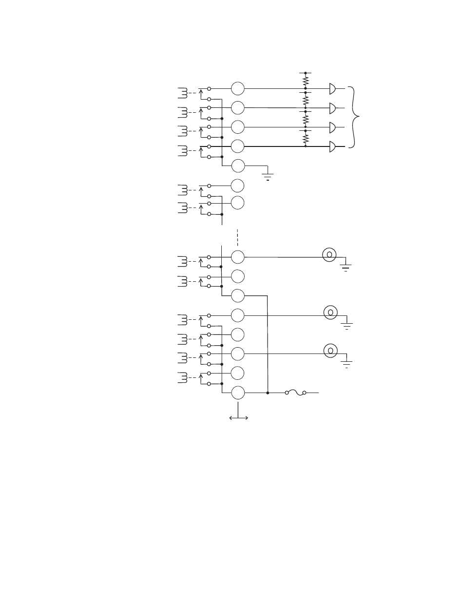
Figure 6. Tally and GPI Output Connection Example
The example shown in
illustrates two common buses. The first
four outputs (COMMON A) have the common bus tied to ground. This
drives a logic system. The last outputs (COMMON G and COMMON H)
have the common bus tied to +12 volts. This drives a tally lamp system.
Although diagram shows mechanical relays, the actual outputs are imple-
mented with solid state relays. The solid state relays are bidirectional;
either polarity voltage can be applied. If the switcher GPI/Tally outputs are
used to drive downstream DC relays, be sure to install diodes across the
50-pin Connector
Pin Numbers
1A of 32
2A of 32
3A of 32
4A of 32
5B of 32
6B of 32
27G of 32
28G of 32
29H of 32
30H of 32
31H of 32
32H of 32
Video Processor Frame
User Equipment
Common B
Common A
Common H
Logic
12V Lamp
12V Lamp
12V Lamp
+ 12V DC
Common G
8623266_46
21
5
38
22
37
39
23
48
32
47
49
33
17
50
16