Rear connections, Gsc node bus control connections, Reference manual – Grass Valley EC9535 v.1.1 User Manual
Page 11
3
EC9535
Reference Manual
and in turn, sends commands to the connected router’s control cards. Only the active control
card sends commands. The active control card updates the stand-by control card.
Both the primary control card and the secondary control card receive commands from the
router control system, but only the active control card responds. Because both cards receive
router control system commands, if the active control card fails, the stand-by control card auto-
matically takes over processing without interruption. In addition, the primary control card and
secondary control card communicate with each other. Should either control card fail, the newly
active control card communicates the failure to the router control system.
Four LEDs on the front of the control card indicate the card’s status: low battery (red), alarm
(red), active (amber), and operating normally (green). For more information, see
Indicator LEDs
on page 21.
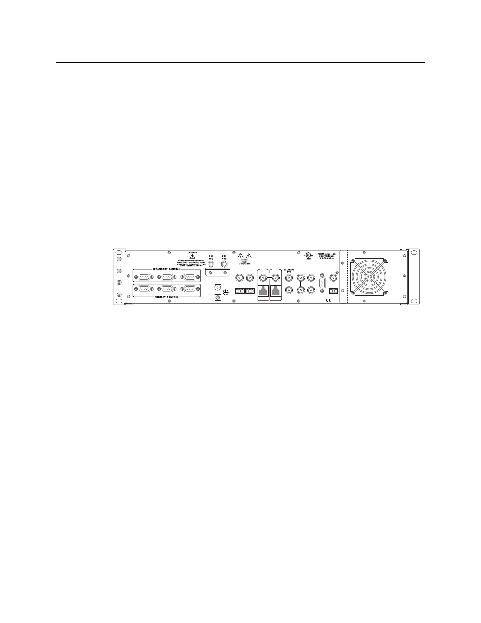
Rear Connections
The rear of the EC9535 frame features a back plate containing several connections for managing
system functions and two power connections:
Fig. 1-3: EC9535 (Rear View)
These connections enable you to connect to a system controller, reference signals, power
sources and system alarms. When facing the rear of the frame, the far right-hand side has a grill
behind which is located the fan for frame cooling. All system and power connections are located
to the left of the fan.
GSC Node Bus Control Connections
The EC9535 GSC Node Bus Converter has one port labeled ‘GSC NODE BUS’, as shown in
Figure 1-4. This connection is used to connect a SMS7000 system controller to the EC9535. In
turn, the EC9535 is connected to a NV8288, NV8288-Plus or NV8500 Family router. Through the
GSC Node Bus connection, the SMS7000 router control system sends commands to both the
EC9535’s primary and secondary control cards. In turn, the control cards forward the commands
VIDEO
REF 2
VIDEO
REF 1
ALARMS
TIME
CODE
LOOP
LOOP
LOOP
SEC
CTRL
LOOP
THRU
10/100 BT
10 B 2
PRI
CTRL
10 B 2
10/100 BT
AES
REF 1
AES
REF 2
DIAG
DIAG
CTRL 1
CTRL 2
CTRL 1
CTRL 2
E146905