Ethernet connections, Aes reference connections, Ethernet connections aes reference connections – Grass Valley EC9535 v.1.1 User Manual
Page 13: The ‘diag’ port(s), Reference manual, Fig. 1-6: diagnostic connections (rear view), Fig. 1-7: ethernet control connections (rear view), Diagnostic connections
5
EC9535
Reference Manual
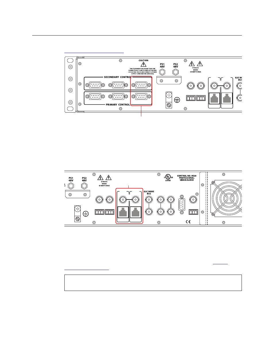
connects to EC9535’s secondary (optional for redundancy) control card. For instructions, see
Fig. 1-6: Diagnostic Connections (Rear View)
Ethernet Connections
The EC9535 has two Ethernet ports, labeled ‘10/100BT’, as shown in Figure 1-7. These ports are
divided into two sets, one primary (‘PRI CTRL’) and one secondary (‘SEC CTRL’). These connec-
tions can be used to connect to a PC running UniConfig. However, in general these connections
are not used at this time and provided for future network use.
Fig. 1-7: Ethernet Control Connections (Rear View)
In order for EC9535 to communicate with UniConfig through an Ethernet connection, you must
configure an IP address for each of EC9535’s control cards. The IP address is set using UniConfig.
However, UniConfig runs on a PC and cannot communicate with EC9535 until an IP address has
been entered. Therefore, you must use a serial connection
—
the ‘DIAG’ port(s)
—
to communi-
cate with the computer (PC) running UniConfig to define the IP address(es). See
AES Reference Connections
The AES reference is used for clock generation, which provides a timing reference for AES
synchronous signals and for timing circuits on the EC9535 control card. This reference is not
LOO
SEC
CTRL
LOOP
THRU
10/100 BT
10 B 2
PRI
CTRL
10 B 2
10/100 BT
AES
REF 1
AES
REF 2
DIAG
DIAG
CTRL 1
CTRL 2
CTRL 1
CTRL 2
Diagnostic Connections
VIDEO
REF 2
VIDEO
REF 1
ALARMS
TIME
CODE
LOOP
LOOP
LOOP
SEC
CTRL
LOOP
THRU
10/100 BT
10 B 2
PRI
CTRL
10 B 2
10/100 BT
AES
REF 1
AES
REF 2
DIAG
DIAG
E146905
Ethernet
Connections
If using an Ethernet connection, 50ohm terminators must be installed on the ‘10 B 2’
connectors.