Aes synchronous (balanced and unbalanced), Madi (unbalanced), Aes synchronous (balanced and – Grass Valley NV7512 v.1.3 User Manual
Page 37: Unbalanced), Introduction
NV7512 Audio Router • User’s Guide
27
1. Introduction
Active Cards
AES Synchronous (Balanced and Unbalanced)
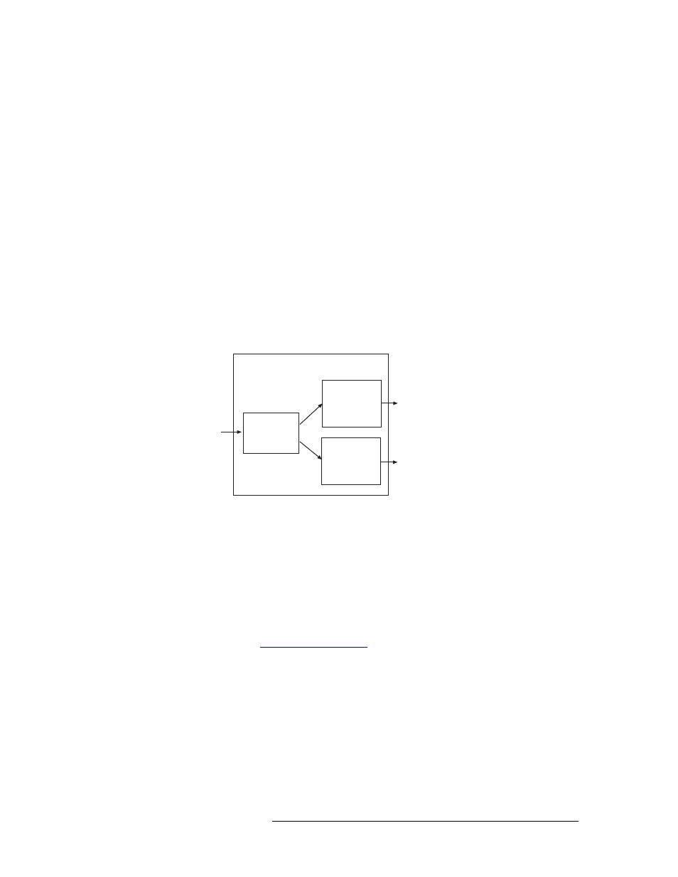
The AES synchronous output card (EM0489) receives outgoing signals from the crosspoint card
(via the motherboard) and forwards the signals to local I/O connectors: DIN 1.0/2.3 for unbalanced
signals and DB25 for balanced signals.
The output card receives up to 32 stereo signals. Inputs are sent to reformatters that rejoin right and
left channels, channel status information, and user bits to create an AES signal. The reformatter
then creates two copies of the signal, forwarding one copy to a cable driver and one copy to a
32 x 1 monitor Mux. The cable driver forwards the signal to local I/O connectors for distribution.
The 32 x 1 Mux forwards the signal to the motherboard, which forwards the signal to the monitor
card for monitoring.
Signals sent to the output card may not be Z-bit or block-aligned. To manage these signals, the out-
put card delays the right channel’s status bits to align them with the left channel’s status bits. If the
source selection for the left channel changes, the right channel status bits are re-aligned with the
new left channel’s status bits. Only the right channel’s status bits are delayed; the audio sample is
not delayed.
Figure 1-20 shows the signal flow for an AES synchronous output card.
Figure 1-20. AES Synchronous Output Card Block Diagram
MADI (Unbalanced)
The MADI output card (EM0477) receives outgoing signals from the crosspoint card (via the moth-
erboard) and forwards the signals to local BNC connectors. All 64 channels can be distributed
through a single connector, or divided between two MADI connectors.
Using DIP switches on the output card, channels can be allocated between the two BNC connec-
tors. In addition, the sample rate of the MADI signals, whether standard or legacy format, can be
set and if channel status data remains untouched or forced to match common professional data. For
more information, see
The MADI output card can receive up to 64 audio channels. Each signal is forwarded to a receiver
that feeds the signal to a reformatter that rejoin right and left channels, channel status information,
and user bits to create a MADI signal. The reformatter sends the signal to a cable driver, which for-
wards the signal to local I/O connectors for distribution.
For monitoring purposes, a copy of the digital audio channels are sent to the monitoring card prior
to encoding. The data is 48
kHz and AES format.
32 x 1
MUX
Cable
Driver
Coaxial
Connector
(up to 32)
Monitor
One
Crosspoint
Card
(Slot determines
signals forwarded
to output card)
Reformatter
Output Card