Cabling requirements, Binding disk modules into groups – Grass Valley PFR 500/E Dec 12 2002 User Manual
Page 27
Cabling requirements
20 September 2002
PFR 500/E Instruction Manual
27
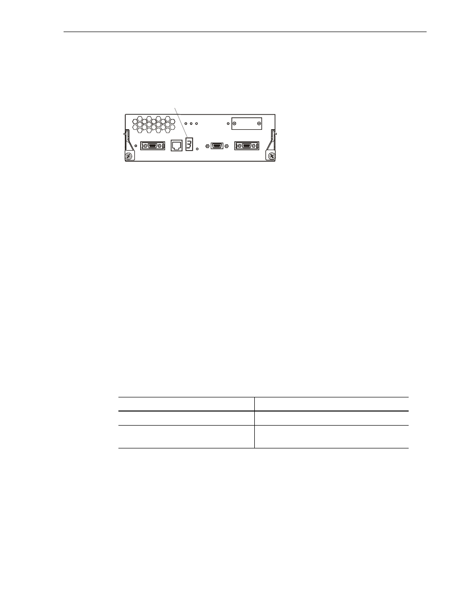
After the chassis addresses have been set and the chassis powered-up, the chassis address
is displayed on the 7-segment display LED as shown.
Cabling requirements
It is recommended that you use the copper Fibre Channel cables shipped with your
PFR500 when making connections.
Any copper cables you use must meet the appropriate standards for 1-Gbit FC-AL loops.
Such cables are fully shielded, twin-axial, full-duplex cables with DB-9 connectors.
Cables greater than 10 meters must be equalized; cables equal to or less than 10 meters
do not need to be equalized. Do not use copper cables longer than 15 meters for any Fibre
Channel connection in a Profile system.
PFR500 and PFR 500E interconnections should maintain LBB consistency. That is, one
FC loop should connect the PFR500’s RAID Controller A and each PFR500E’s LBB A.
The other FC loop should connect the PFR500/E’s RAID Controller B and each
PFR500E’s LBB B.
Do not leave an unused (that is, dangling) cable connected to a Fibre Channel port
because it may cause excess noise on the loop.
Binding disk modules into groups
After cabling a PFR500 and any PFR500Es, you must bind disk modules into LUNs
using a GVG Disk Utility provided by Grass Valley Group. Refer to the appropriate
manual for information on using the GVG Disk Utility to bind drives.
Type of PFR 500/E installation
Manual to use for binding procedures
Part of a Media Area Network
Media Area Network Instruction Manual
Connected directly to a Profile XP Media
Platform as local storage
PVS Installation Guide (for your Profile XP model) or
the Profile XP System Guide
2792
7-Segment Display LED