Interpreting rear panel status leds, Chapter 3 servicing the pfr500/e – Grass Valley PFR 500/E Dec 12 2002 User Manual
Page 38
Chapter 3 Servicing the PFR500/E
38
PFR 500/E Instruction Manual
20 September 2002
Interpreting rear panel status LEDs
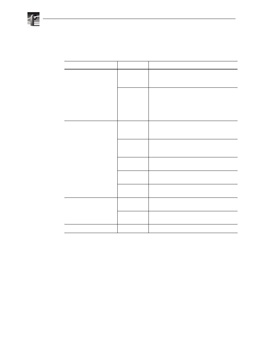
Refer to the following table to interpret rear panel LEDs on FRUs.
Module
LED Name
Meaning
Loop Bypass Board
Loop
LED is ON when the Fiber Channel port does not
detect a valid Fibre Channel signal on the GBIC.
LED is OFF when signal is valid.
7-segment LED
Chassis number and event code display. Refer to
“LBB 7-segment display codes” on page 39
Flashing decimal point indicates heartbeat for
communication between LBB modules. Solid
indicates LBB has critically failed (steady for more
than 30 seconds).
RAID Controller
Host Loop
LED is ON when the Fiber Channel port does not
detect a valid Fibre Channel signal on the GBIC.
LED is OFF when signal is valid.
Host RDY
LED is ON when the host port is initialized and
ready for communication. LED OFF indicates the
RAID Controller is not fully initialized.
Disk ACT
LED is ON when there is disk activity, i.e. data
packets on the disk loops.
Host ACT
The host activity LED is ON when there is host port
activity, i.e. data packets on the host loop.
Tx and Rx
LEDs indicate Ethernet port transmit and receive
status.
Power Supply
Output Good
LED is ON (green) when power supply output is
good.
Fault
LED is ON (amber) when there is a fault in the
power supply.
Fan Module
Fault
LED is ON (red) when there is a fan failure