Location of circuit board mounting screw – Grass Valley Profile CD-ROM Drive User Manual
Page 55
Advertising
Verifying the Parallel Port Configuration
CD-ROM Instructions
55
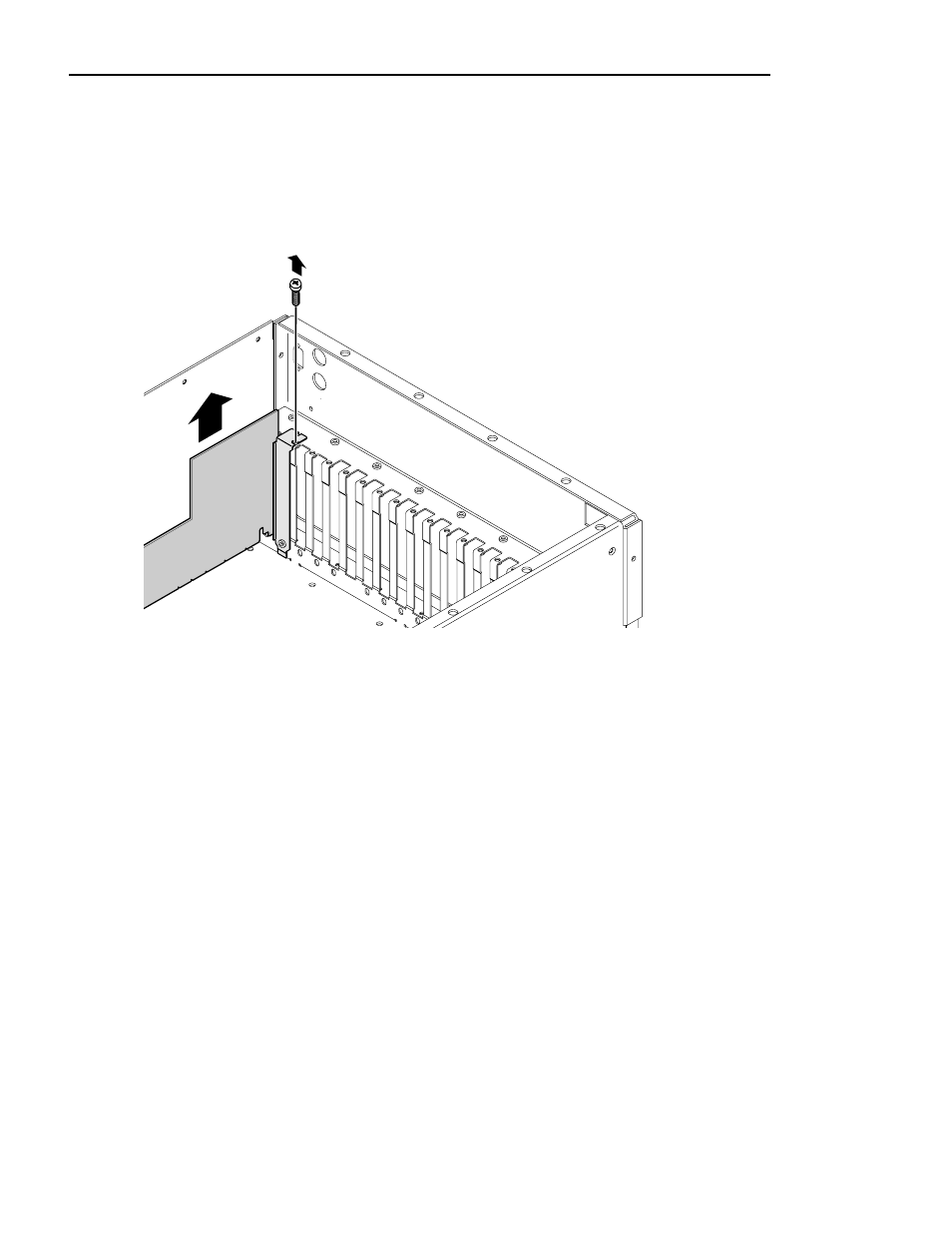
6. The VGA-I/O board is located in slot J2. Remove the circuit board mounting
screw as shown in Figure 15. If the VGA monitor cable is connected to the
board disconnect it now.
Figure 15. Location of circuit board mounting screw
NOTE: See “General Installation Instructions” on page 17 for
proper circuit board handling warnings.
7. Carefully grasp the board and lift upward to free the circuit board from the
motherboard connector. In some cases, it may be necessary to remove the board
in the adjacent slot J3 before removing the VGA-I/O board.
8. Set the switches on your VGA-I/O board as shown in Figure 16 for the CEX595
9897-24
Advertising