Grass Valley Trinix Back-Up Power Supplies Nov 16 2012 User Manual
Page 40
40
Trinix — Installation and Service Manual
Section 3 — Installation for Legacy Frames
e.
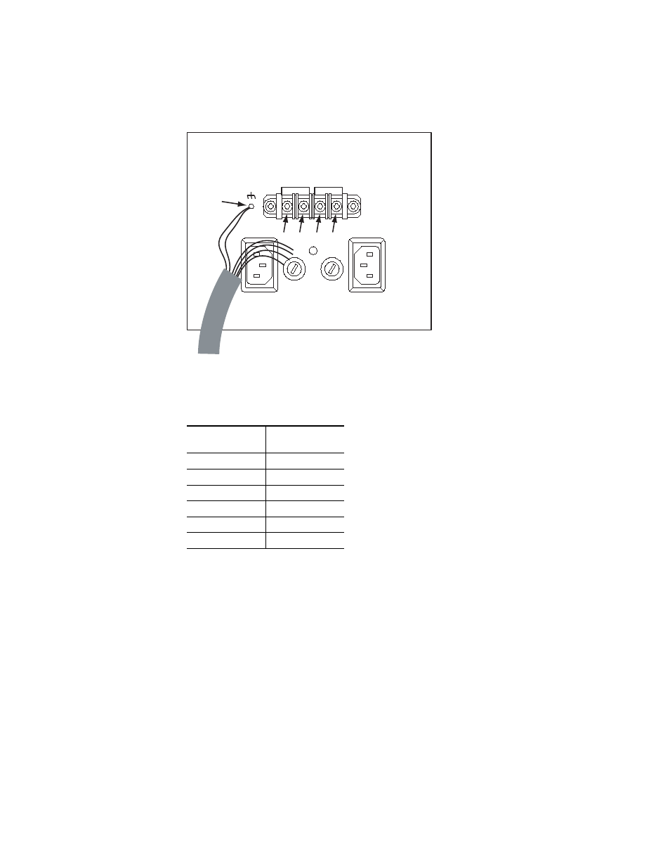
Connect the supplied external power supply cables as shown in
.
Figure 3. DV-33128/256 External Power Supply Wiring (Partially Complete)
f.
All connections to the router itself are now done. Double check all
wiring.
3.
Connect the AC or DC power cords to the external power supplies.
4.
At the front of the external power supply chassis, screw in each supply.
Verify that the top two LEDs on the front of each supply are green (AC
good/DC good), and that the fans all rotate.
5.
Restore power to the Trinix internal power supplies.
6.
Check the DC voltage now being provided at the Trinix “DC In”
connectors. Voltage should be between 47 and 52 VDC. If not, contact
Grass Valley Technical Support.
Table 1. External Power Supply Wiring (Complete)
Wire Color
Connect to
Terminal
Yellow/green
(1)
Black
(1)
Red
(2)
Blue
(3)
White
(4)
Yellow
(5)
DC IN -
DC IN +
PS B
PS A
(1)
(2)
(3)
(4)
(5)
8443_15