Grass Valley Zodiak Installation Planning Guide User Manual
Page 23
Zodiak Installation Planning Guide
23
Optional Components
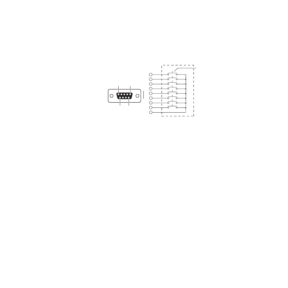
Joystick Override
A user fabricated cable, external switch, and a 9-pin D connector are
required to implement camera joystick override. Use shielded cable
and connect the shield to the metal connector shell when fabricating the
joystick override cable. Refer to
Figure 24. KAL-24AUX Joystick Override Connector Cable Wiring
Communications Bus
The communications bus cable connector shipped with each panel
must be attached to the supplied cable or a user fabricated cable (refer
to
). The supplied cable is 164 ft (50 m) long and has a pre-
wired 9-pin D connector on one end. If fabricating a cable, use a
shielded twisted pair cable such as Belden 8451 and refer to
wiring connections.
Thirty-two 24-Crosspoint Remote Aux panels can be daisy-chained on
a single serial control port on the Zodiak Video Processor frame, but the
total length of cable in the panel daisy-chain cannot exceed 1000 ft
(320 m). Allow enough cable to reach each control panel connector, plus
approximately 3 ft (1 m) extra.
Momentary Contact Switches
0619_04_71_r5
Pin 1
Pin 9
Pin 6
Pin 5
Common
1
2
3
4
6
7
8
5
9
D-9 Male
Joystick Override
Connector
(wiring side)