Ed (see, Connects (see, Figure 40 – Grass Valley Zodiak Installation Planning Guide User Manual
Page 35
Zodiak Installation Planning Guide
35
Zodiak System Control Cabling
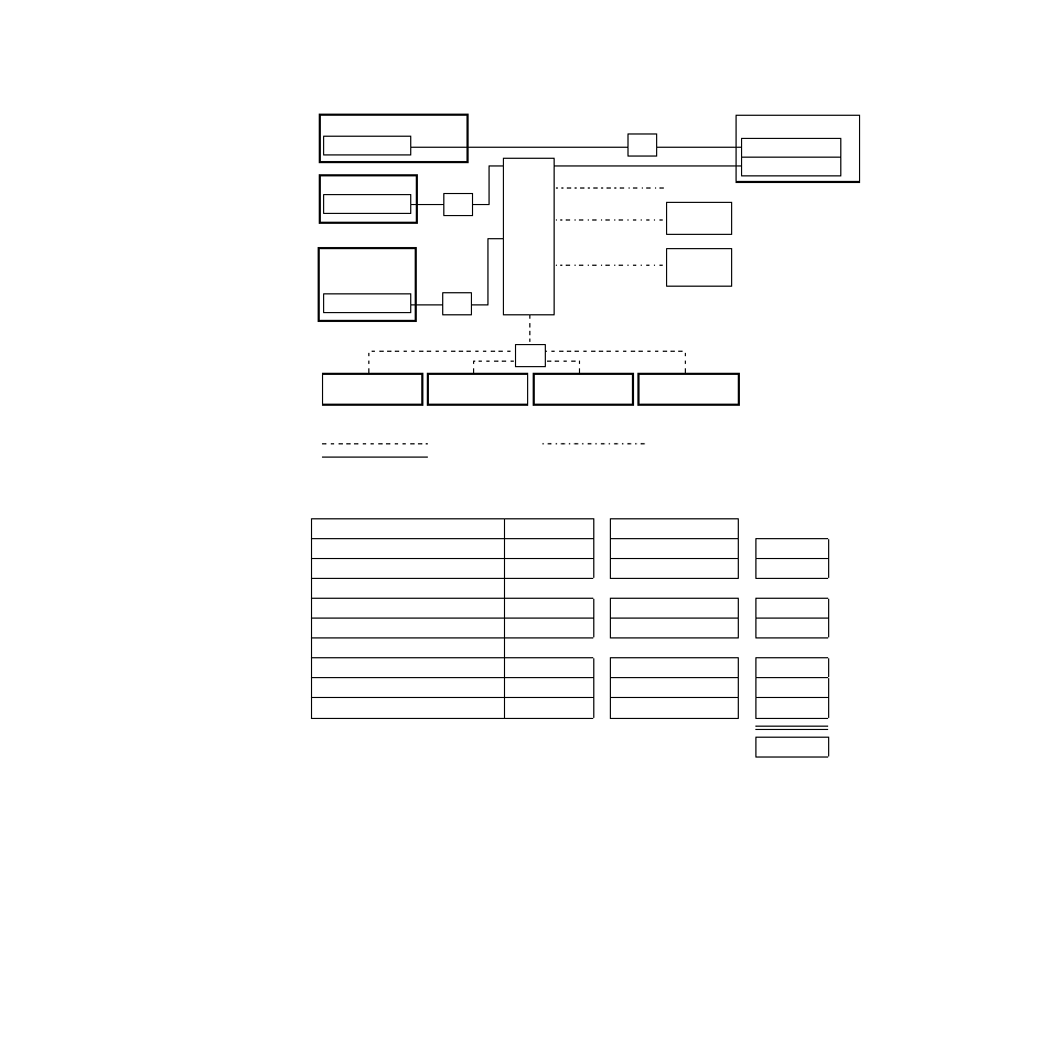
Figure 40. Example Topography Requiring an Ethernet Switch
Standard System Components
Ports Required
Number of Components
Frame
a
a
The connection from the Main panel to the Video Processor frame is always a direct connection and does not require
a port.
NA
x
--
=
--
Menu Panel
1
x
1
=
1
Zodiak Options
32-Crosspoint Remote Aux Panel Hub
1
b
b
No port required if option not installed.
x
(# of Hubs)
=
Additional Zodiak Menu Panel
1
Other Ethernet Devices
Facility Intranet
1
x
=
PC with Still Store Graphics
1
x
=
PC running Zodiak Menu application
1
x
=
Total Number of Ports Required:
Facility Intranet
PC with
Still Store Graphics
8096_00_21_r3
Real Time Processor
Main Panel
10BaseT Facility LAN
100BaseT Facility LAN
10/100BaseT Facility Intranet
32-XPT Remote
Aux Panel
(Option)
32-XPT Remote
Aux Panel
(Option)
32-XPT Remote
Aux Panel
(Option)
32-XPT Remote
Aux Panel
(Option)
Ethernet
Hub1
Video Processor Frame
Panel LAN
1 Use hubs to exceed 328 ft (100 m) cable limitations.
Menu Panel
Menu System Processor
Ethernet
Switch
Ethernet
Hub1
Ethernet
Hub1
Additional
Menu Panel
(Option)
Menu System Processor
Ethernet
Hub1
Menu LAN
PC running
Zodiak Menu
application