4 face milling (cycle 233), Cycle run, Face milling (cycle 233) – HEIDENHAIN TNC 128 (77184x-02) User Manual
Page 437
FACE MILLING (Cycle 233)
17.4
17
TNC 128 | User's Manual HEIDENHAIN Conversational Programming | 5/2014
437
17.4
FACE MILLING (Cycle 233)
Cycle run
Cycle 233 is used to face mill a level surface in multiple infeeds
while taking the finishing allowance into account. You can also
define side walls in the cycle, which are then taken into account
when machining the level surface. The cycle offers you various
machining strategies:
Strategy Q389=0
: Meander machining, stepover outside the
surface being machined
Strategy Q389=1
: Meander machining, stepover at the edge of
the surface being machined
Strategy Q389=2
: The surface is machined line by line with
overtravel; stepover after retracting at rapid traverse
Strategy Q389=3
: The surface is machined line by line without
overtravel; stepover after retracting at rapid traverse
Strategy Q389=4
: Helical machining from the outside toward
the inside
1 From the current position, the TNC positions the tool at rapid
traverse
FMAX to the starting point
1
in the working plane: The
starting point in the working plane is offset from the edge of
the workpiece by the tool radius and the safety clearance to the
side.
2 The TNC then positions the tool at rapid traverse
FMAX to the
set-up clearance in the spindle axis.
3 The tool then moves in the spindle axis at the pre-positioning
feed rate Q253 to the first plunging depth calculated by the
TNC.
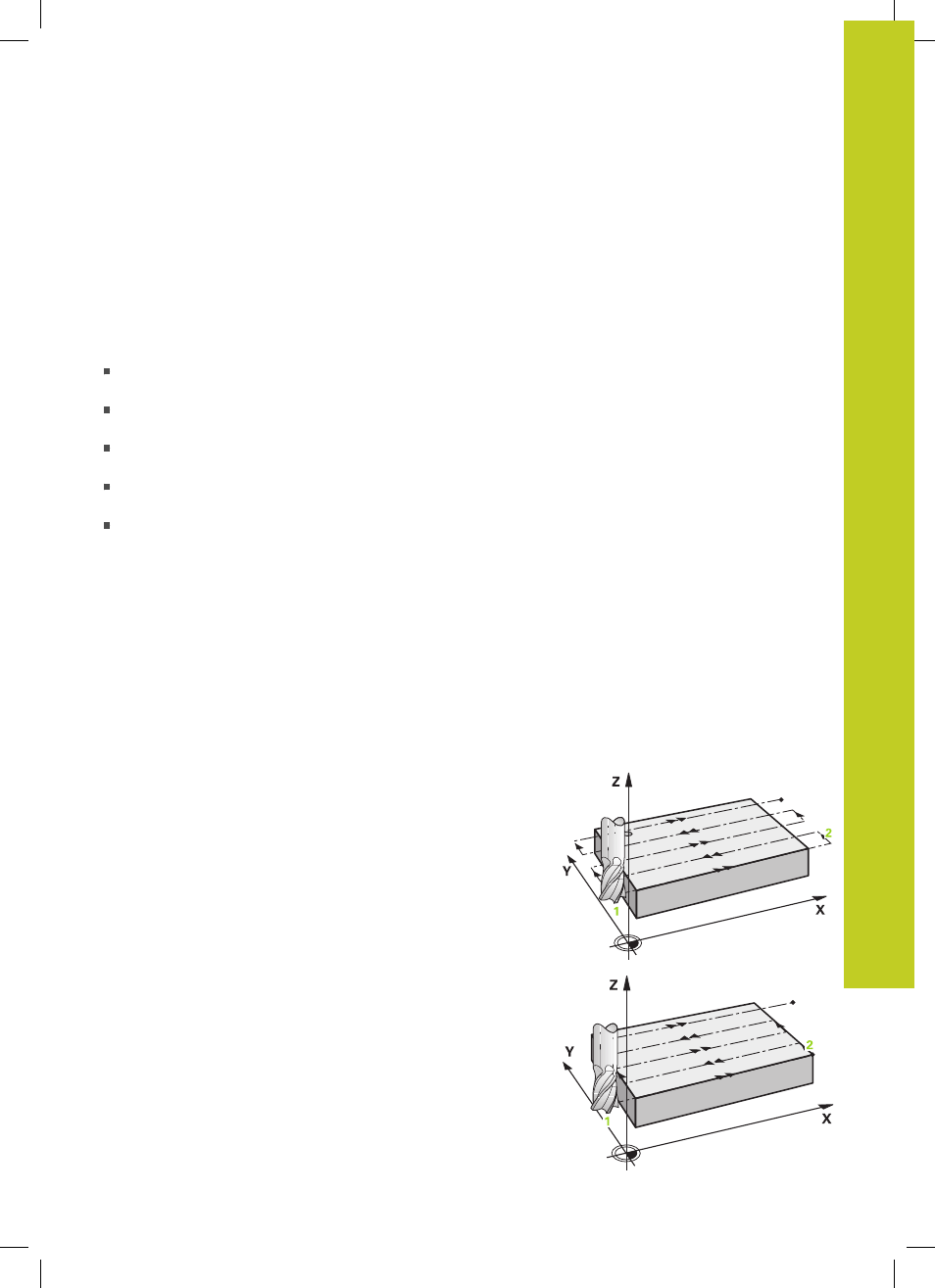
Strategies Q389=0 and Q389 =1
The strategies Q389=0 and Q389=1 differ in the overtravel during
face milling. If Q389=0, the end point lies outside of the surface. If
Q389=1, it lies at the edge of the surface. The TNC calculates the
end point
2
from the side length and the safety clearance to the
side. If the strategy Q389=0 is used, the TNC additionally moves
the tool beyond the level surface by the tool radius.
4 The TNC moves the tool to the end point
2
at the programmed
feed rate for milling.
5 Then the TNC offsets the tool to the starting point in the next
pass at the pre-positioning feed rate. The offset is calculated
from the programmed width, the tool radius, the maximum path
overlap factor and the safety clearance to the side.
6 The tool then returns at the feed rate for milling in the opposite
direction.
7 The process is repeated until the programmed surface has been
completed.
8 The TNC then positions the tool at rapid traverse
FMAX back to
the starting point
1
.
9 If more than one infeed is required, the TNC moves the tool in
the spindle axis to the next plunging depth at the positioning
feed rate.