Fundamentals of positioning, Coordinate system and coordinate axes – HEIDENHAIN NC 124 User Manual
Page 11
1
Fundamentals of Positioning
TNC 124
11
1
0° 90°
90°
0°
30°
30°
60°
60°
Greenwich
+X
+Y
+Z
+X
+Z
+Y
Y
B+
V+
X
Z
C+
A+
W+
U+
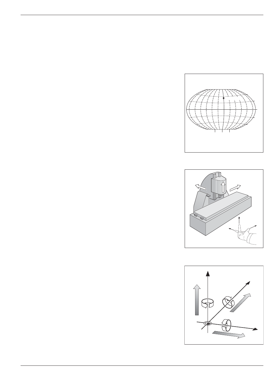
Fig. 1.3:
Main, additional and rotary axes in
the Cartesian coordinate system
Fig. 1.2:
Designations and directions of the
axes on a milling machine
Fig. 1.1:
The geographic coordinate system
is an absolute reference system
Fundamentals of Positioning
Coordinate system and coordinate axes
Reference system
In order to define positions on a surface, a reference system is
required. For example, positions on the earth's surface can be
defined absolutely by their geographic coordinates of longitude and
latitude. The term coordinate comes from the Latin word for that
which is arranged. In contrast to the relative definition of a position
that is referenced to a known location, the network of horizontal and
vertical lines on the globe constitutes an absolute reference system.
The Greenwich observatory illustrated in Fig. 1.1 is located at 0° lon-
gitude, and the equator at 0° latitude.
Cartesian coordinate system
On a TNC-controlled milling or drilling machine tool, workpieces are
normally machined according to a workpiece-based Cartesian coordi-
nate system (a rectangular coordinate system named after the
French mathematician and philosopher Renatus Cartesius, who lived
from 1596 to 1650). The Cartesian coordinate system is based on
three coordinate axes designated X, Y and Z which are parallel to the
machine guideways.
The figure to the right illustrates the right-hand rule for remembering
the three axis directions: the middle finger is pointing in the positive
direction of the tool axis from the workpiece toward the tool (the Z
axis), the thumb is pointing in the positive X direction, and the index
finger in the positive Y direction.
Axis designations
X, Y and Z are the main axes of the Cartesian coordinate system.
The additional axes U, V and W are secondary linear axes parallel to
the main axes. Rotary axes are designated as A, B and C (see Fig.
1.3).