Cycle parameters – HEIDENHAIN TNC 320 (340 55x-05) Cycle programming User Manual
Page 302
302
Touch Probe Cycles: Automatic Measurement of Workpiece Misalignment
14.5 BA
SIC R
O
T
A
TION Compensation via Rotary Axis (Cy
c
le 403,
DIN/ISO:
G403)
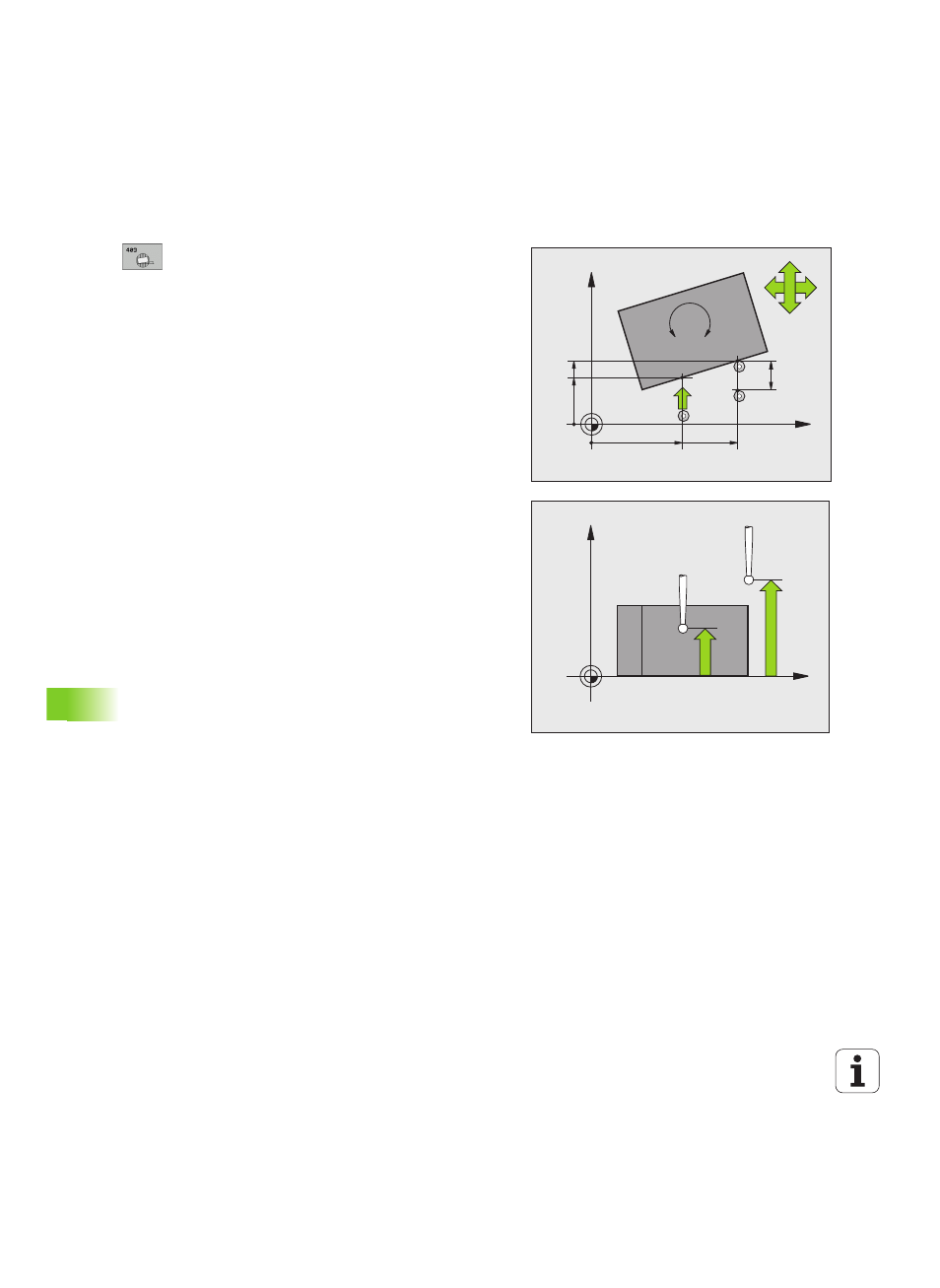
Cycle parameters
U
1st meas. point 1st axis Q263 (absolute): Coordinate
of the first touch point in the reference axis of the
working plane. Input range -99999.9999 to
99999.9999
U
1st meas. point 2nd axis Q264 (absolute):
Coordinate of the first touch point in the minor axis of
the working plane. Input range -99999.9999 to
99999.9999
U
2nd meas. point 1st axis Q265 (absolute):
Coordinate of the second touch point in the reference
axis of the working plane. Input range -99999.9999 to
99999.9999
U
2nd meas. point 2nd axis Q266 (absolute):
Coordinate of the second touch point in the minor axis
of the working plane. Input range -99999.9999 to
99999.9999
U
Measuring axis Q272: Axis in which the
measurement is to be made:
1: Reference axis = measuring axis
2: Minor axis = measuring axis
3: Touch probe axis = measuring axis
U
Traverse direction 1 Q267: Direction in which the
probe is to approach the workpiece:
–1: Negative traverse direction
+1: Positive traverse direction
U
Measuring height in the touch probe axis Q261
(absolute): Coordinate of the ball tip center (= touch
point) in the touch probe axis in which the
measurement is to be made. Input range
-99999.9999 to 99999.9999
U
Set-up clearance Q320 (incremental): Additional
distance between measuring point and ball tip. Q320
is added to SET_UP (touch probe table). Input range
0 to 99999.9999
X
Y
Q266
Q264
Q263
Q272=1
Q265
Q272=2
+
+
Q267
A
B
C
SET_UP(TCHPROBE.TP)
+
Q320
X
Z
Q261
Q260