Tire size and carrying capacity chart – ShoreLand'r SLB30BLW User Manual
Page 9
Midwest Industries, Inc.
Ida Grove, IA 51445
800.859.3028
www.shorelandr.com
0003432
Page 9
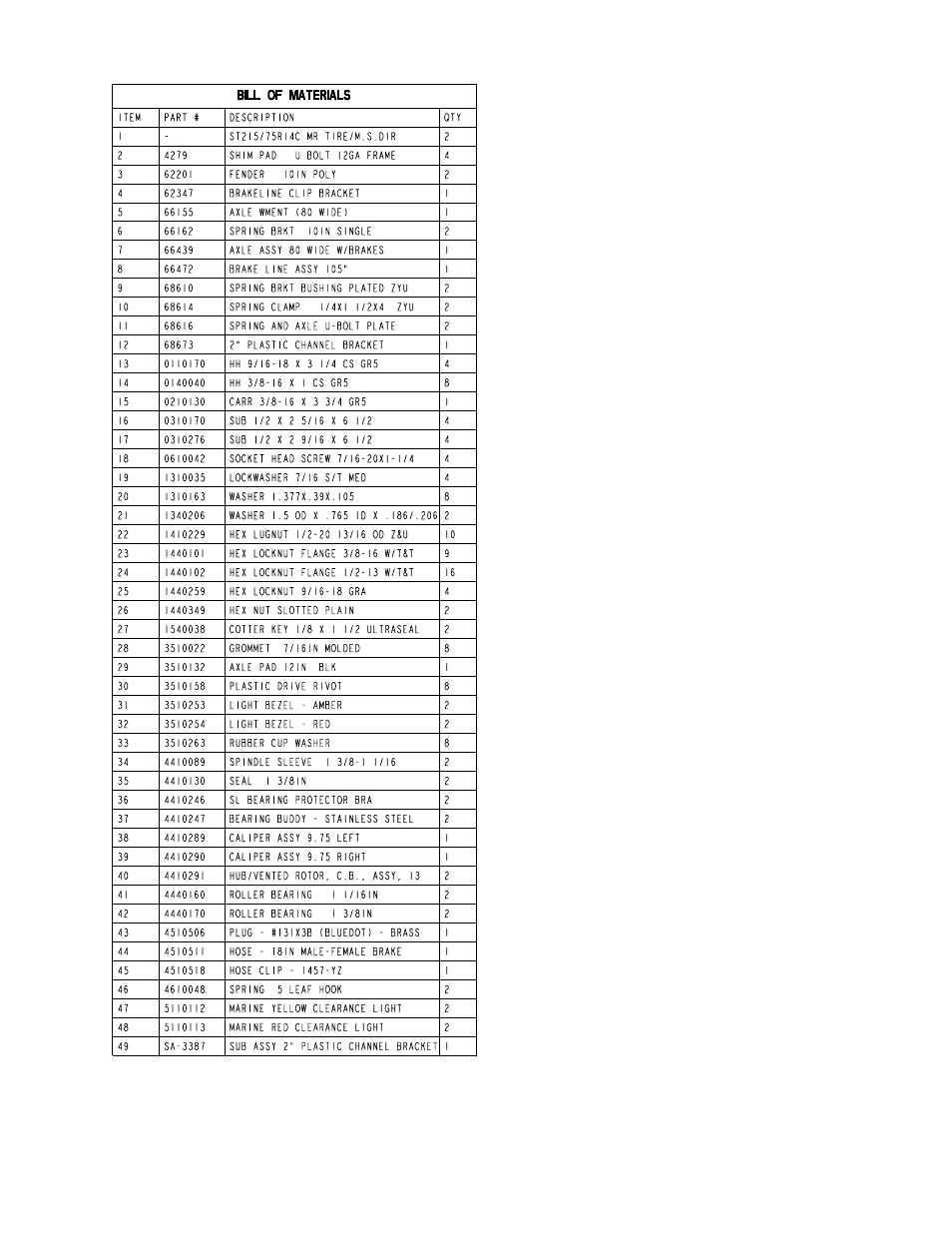
Tire Size and Carrying Capacity Chart
Tire Size ....................... ST215/75R 14-C
GVWR .......................... 3740 lb.
Carrying Capacity ....... 3000 lb.
Axle .............................. Disc Brakes
Refer to the tire side wall for correct tire pressure.
SPRINGS
Position the axle so it is properly aligned with the trailer and
the brake calipers are located on the back side of the axle.
(See Diagram D).
Place the springs on the top side of the spring pads welded
to the axle. (See chassis Diagram D). Note that the hook
end of the spring must be mounted to the rear of the trailer.
Place a spring clamp on the top center of the spring as
shown. Next place the 1/2” x 6-1/2” U-bolts down over the
top of the spring clamp, spring and axle as shown.
Place the spring and axle U-bolt plate onto the ends of the
two U-bolts just installed. Secure in place with 1/2” lock nuts.
Thread onto the U-bolts but do not tighten securely until the
complete unit is in position on the trailer. Repeat on the other
spring.
AXLE
Place one of the spring bracket bushings into the rear of the
spring bracket and secure with a 9/16” x 3 1/4” hex bolt and
hex lock nut.Repeat in other spring bracket.
Position the axle under the frame, then hook the loop end of
the spring around the bushings just installed. Note that if the
axle is positioned too low when trying to hook, the loops will
not hook around the bushings.
Raise the front of the springs up so they align with the front
hole of the spring bracket. Secure in place with 9/16” x 3-
1/4” hex bolts and lock nuts.
Tighten all axle U-bolts and spring bolts not tightened at this
time.
ONE AXLE BRAKE INSTALLATION
Cut the tape securing the brake line hose to the axle. Re-
move the brass plug from the port in the brass block on the
right brake caliper. Thread in the male end of the brake hose
and tighten to 6-8 ft. lb. or else 72-96 in. lb. of torque.
DO NOT OVER TIGHTEN. Over tightening will cause the
brass block to crack and then leak.
Place the other end of the hose through the hole in the brake
line clip bracket and secure with the U-shaped hose clip pro-
vided.