2 connection area of the inverter, Connection area of the inverter – SMA SB 3000-US User Manual
Page 37
Advertising
SMA America, LLC
6 Electrical Connection
Installation Manual
SB30-40-US-IA-en-34
37
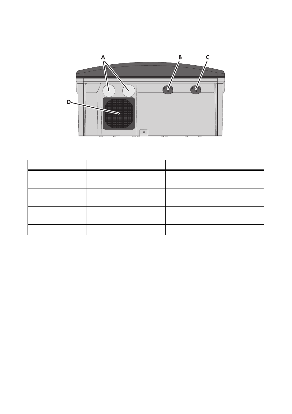
6.2.2 Connection Area of the Inverter
Figure 13: Terminals on the underside of the inverter
Position
Designation
Explanation
A
Enclosure opening with filler-
plug
For inserting the communication cable
B
Enclosure opening with rubber
grommet
For inserting the DC cable of the
DC Disconnect
C
Enclosure opening with rubber
grommet
For inserting the AC cable of the
DC Disconnect
D
Fan guard
‒
Advertising
This manual is related to the following products: