Connecting a modem, 3 connecting a modem – SMA Sunny Boy Control Light User Manual
Page 24
Sunny Boy Control Light
Chapter 3: Installing of the connectors
SUNBCL-11:NE
- 24 -
SMA Regelsysteme GmbH
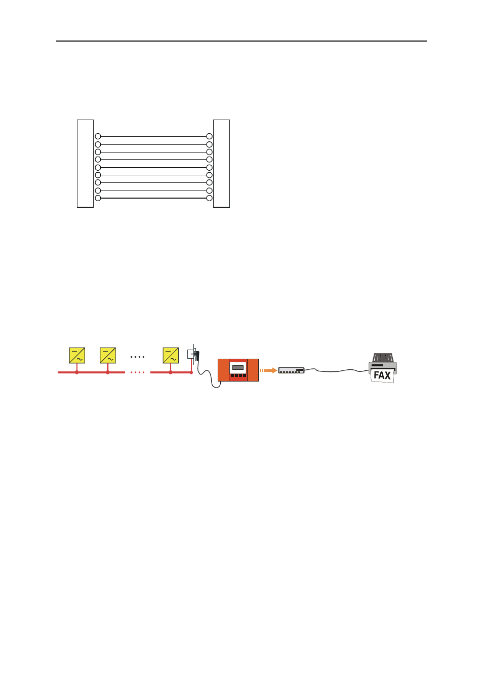
Serial RS232 Cable DSUB9<>DSUB9
PIN
1
2
3
4
5
6
7
8
9
DSUB9-Socket
DSUB9-Socket
PIN
1
2
3
4
5
6
7
8
9
Fig. 3.9: Serial cable DSUB9<>DSUB9
For further information on how to connect a modem to the Sunny Boy Control please
read chapter 3.3 "Connecting a Modem".
3.3 Connecting a Modem
RS232
telephone line
Modem
Sunny Boy
Control
Sunny Boy
Sunny Boy
230 V / 50 Hz
Sunny Boy
Fig. 3.10: Connecting a Modem
You need an external modem for connecting the Sunny Boy Control Light to the
telephone line. We recommend „Microlink 56k“ from Elsa in most cases - check with
SMA before you try to connect a modem. Note that the modem must be Fax class 2
compliant in order to reliably communicate with the Sunny Boy Control Light. The
list of used AT-commands is included in this installation guide (See chapter 7.5, AT-
Modem Cable to the Sunny Boy Control Light
Connect the modem (port: V24/RS232C) to the Sunny Boy Control Light (port: PC)
with a RS232 cable. Use the cable supplied with the modem and not the cable that
you use for connecting the Sunny Boy Control Light since these are different.