5 installation procedure – Yaskawa 1000 Series Drive Option - Analog Monitor User Manual
Page 18
5 Installation Procedure
18
YASKAWA ELECTRIC TOBP C730600 40E 1000-Series Option AO-A3 Installation Manual
5.
Wire the customer-supplied circuit to the terminal block on the option. Refer to
for wiring instructions.
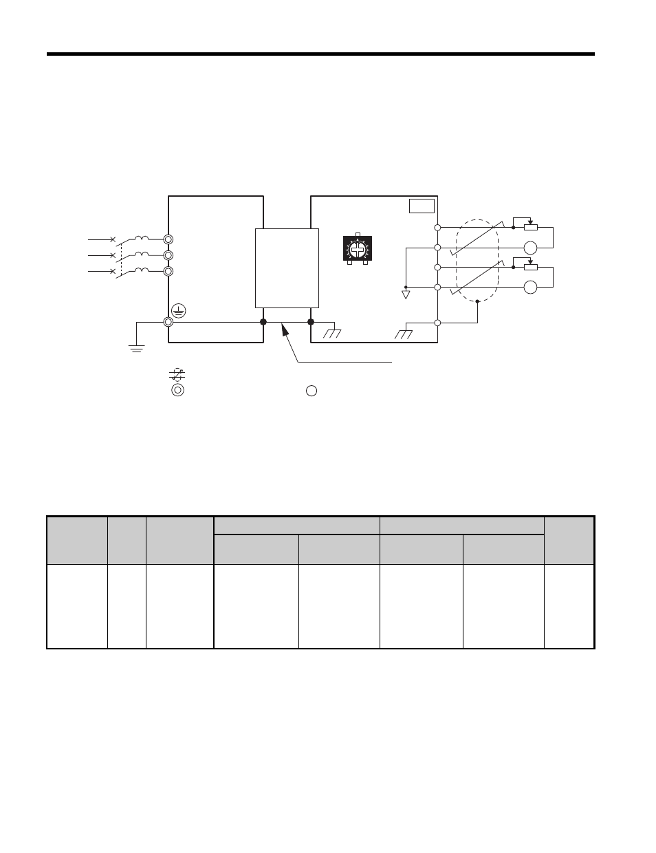
Connection Diagram
Refer to
on page
for a detailed description of the option board terminal
functions. To ensure accurate control, use stable power supply for the voltage
reference source.
Figure 8
Figure 8 Option Connection Diagram
NOTICE: Do not adjust the potentiometers on the option. The potentiometers are factory set and may
change the voltage output characteristics and cause output signal inaccuracy if misadjusted.
Wire Gauges and Tightening Torques
Wire gauge and torque specifications are listed in
Table 4
.
Table 2 Wire Gauges and Tightening Torques
Terminal
signal
Screw
Size
Tightening
Torque
Nxm (inxlb)
Bare Cable
Ferrule-Type Terminals
Wire
Type
Recomm.
Gauge mm
2
Applicable
Gauges mm
2
Recomm.
Gauge mm
2
Applicable
Gauges mm
2
V1, V2,
AC, FE
M2
0.22 to 0.25
(1.95 to 2.21)
0.75
(18 AWG)
Stranded wire:
0.25 to 1.0
(24 to 17 AWG)
Solid wire:
0.25 to 1.5
(24 to 16 AWG)
0.5
(20 AWG)
0.25 to 0.5
(24 to 20 AWG)
Shielded
twisted
pair, etc.
Twisted-pair shielded line
Main circuit terminal
Control circuit terminal
V1
AC
AC
V2
FE
AO-A3
Monitor
CN5
R/L1
S/L2
T/L3
TB1
FE
FM
AM
+
−
+
−
Unit
Ground wire
AO