Prior to installing the option card, Installing the option card – Yaskawa 1000 Series Drive Option - CANopen Technical Manual User Manual
Page 11
5 Installation Procedure
YASKAWA ELECTRIC SIEP C730600 45B 1000-Series Option SI-S3 Technical Manual
11
◆
Prior to Installing the Option Card
Prior to installing the CANopen Option, wire the drive and make necessary connections to the drive terminals. For more information on wiring and
connecting the drive, refer to the technical manual for the drive the CANopen option card is connected to. Verify that the drive runs normally
without the option installed.
◆
Installing the Option Card
1.
Shut off power to the drive, wait the appropriate amount of time for voltage to dissipate, then remove the operator and front cover. Refer to
the drive technical manual for direction on removing the front cover.
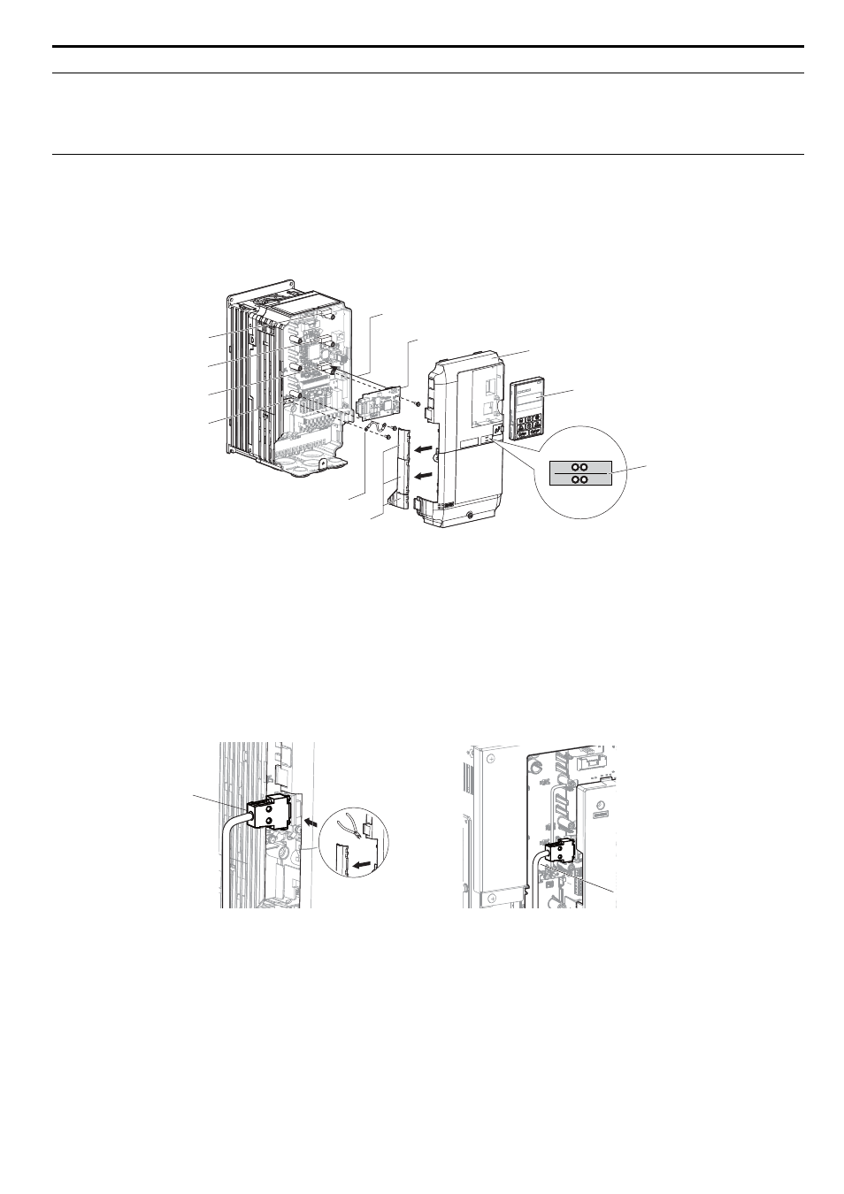
2.
Insert the CN5 connector on the option card into the CN5-A connector on the drive, then fasten it into place using one of the screws included
with the option card.
Connect the ground lead line to the ground terminal using one of the screws delivered with the option card.
Note: There are only two screw holes on the drive for ground terminals. If three option cards are connected, two of the lead lines will need to share the same ground terminal.
Figure 3
Figure 3 Installing the Option Card
3.
Prepare network cable connectors like explained in
on page
. Apply a termination resistor like explained in
if the drive is the last node in the network.
In the drives CIMR-A2A0004 to 0040 and 4A0002 to 0023 the network cable must be routed to the outside through the drive top cover. Use
a pair of wire cutters to cut out the perforated openings at the left side of the top cover. Make sure no sharp edges that can damage the cable
remain.
Drives 2A0056 to 0211, 4A0031 to 0165 have enough space to keep all wiring inside the unit.
Figure 4
Figure 4 Wiring space
4.
Plug in the network cable connector and fix it using the screws at the side of connector.
5.
Place the front cover back onto the drive as it was before.
Note: 1. Take care when wiring the option card so that the front cover easily fits back onto the drive.
2. Install Cable Cover option to maintain the drive Enclosure Type.
6.
Attach the LED label packaged with the option card as shown in
.
7.
Switch on the drive power supply.
An “AEr” Alarm message indicating that the node address is set to 0 will appear on the display. Set the node address in parameter F6-35.
Set the communication speed in parameter F6-36.
8.
Cycle the power supply to activate the changed settings. Installation completed.
A – Insert connector CN5 here
G – Lead line
B – Option card
H – Drive grounding terminal (FE)
C – Front cover
I – Connector CN5-A
D – Operator
J – Connector CN5-B
E – LED label
K – Connector CN5-C
F – Use wire cutters to create an
opening for cable lines
A – Opening for cable lines
(CIMR-A2A0004 to 0040, 4A0002 to 0023)
B – Space for wiring
(CIMR-A2A0056 to 0211, 4A0031 to 0165)
G
K
A
B
D
J
I
H
F
ERR
RUN
E
C
A
B