Basic concepts and principles, Changes from the standard product, Limitations – Yaskawa A1000 User Manual
Page 7
2 Electronic Line Shaft
YASKAWA TM.A1000SW.064 Electronic Line Shaft with Alignment A1000 Custom Software Supplement
7
Basic Concepts and Principles
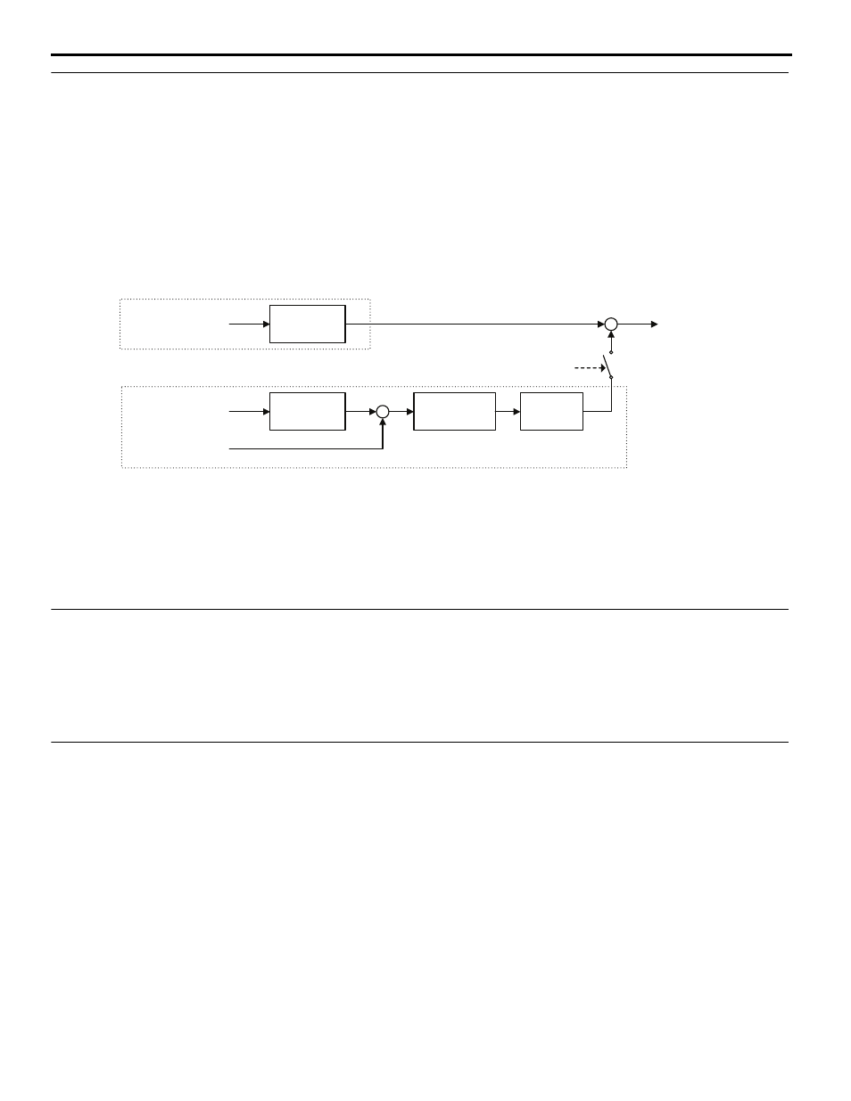
The master encoder signal is fed into a PG option card installed in the CN5-B port of the follower (PG Channel 2). When
using V/f w/PG or CLV control modes, the encoder signal of the follower is fed into a PG option card installed in the
CN5-C port of the follower (PG Channel 1) and the master encoder speed is multiplied by the programmed gear ratio to
determine the frequency reference of the follower.
Setting parameter P1-01 to 4 or 5 configures the drive for ELS and ELS Signed Run modes. These configurations
determine the error between the master and follower position and this error is fed into a PI controller, which is then added
to the previously calculated frequency reference. The position regulator is disabled when the drive is configured only as a
speed follower (non-ELS modes).
Figure 2
Figure 2 Simplified Block Diagram of ELS Function
The Signed Run mode ELS functions identically to the standard ELS mode with the following exceptions:
• When a reverse Run command is given, the follower will match the velocity and phase of the master, but in the opposite
direction (i.e., if the master runs in the forward direction, the follower will run in reverse direction and if the master runs
in the reverse direction, the follower will run in the forward direction).
• When a forward Run command is present, the follower will run in the same direction as the master.
Changes from the Standard Product
• The Motor 2 Selection multi-function input setting is deleted (only Motor 1 can be used).
• The follower drive uses acceleration and deceleration times of zero during Electronic Line Shaft operation
(P1-01 = 4 or 5).
•
PG 2 related parameters F1-31 and F1-32 are always available and no longer require selecting Motor 2 via
digital input.
Limitations
• For ELS and ELS Signed Run modes (P1-01 = 4 or 5), Yaskawa recommends using Closed Loop Vector (A1-02 = 3)
control mode.
• For Speed Follower Both Directions, ELS, and ELS Signed Run modes (P1-01 = 1, 4, or 5), install master and follower
encoder feedback cards and set to quadrature encoder input (F1-21 and F1-37 = 1).
• For Speed Follower Both Directions mode (P1-01 = 1), set the master encoder input to quadrature encoder input
(F1-37 = 1).
• For ELS and ELS Signed Run modes (P1-01 = 4 or 5), express the gear ratio exactly, including remainder, to prevent
phase drift.
• Use the proper option card port for each encoder (PG) input. (CN5-B: Master Encoder, CN5-C: Follower Encoder).
• DriveWorksEZ is not currently supported with software version VSA910030.
• The LED keypad is not fully supported; some alarms and faults may not display properly on the LED keypad.
Gear
Calculation
Gear
Calculation
Master Encoder
Speed
Master Encoder
Pulse Count
Follower Encoder
Pulse Count
+
-
+
+
PI
Controller
Frequency
Reference
ELS Mode
Enabled
Position Error
Accumulator
Speed Calculation
Position Regulator