Yaskawa CM091 User Manual
V7 modbus, Tcp/ip option kit cm091
Yaskawa Electric America, Inc –
www.yaskawa.com
IG.V7.25, Page 1 of 6
Date: 10/08/09, Rev: 09-10
V7 Modbus
®
TCP/IP Option Kit
CM091
1.
Applicable products: Standard V7 drives (CIMR-V7AM*) with Ethernet
specific software installed (Not V74X or V7N). Check V7 monitor U-10 or
the PRG # on the V7 nameplate for version 8340 or 8350 software.
Note: To order a V7 with Ethernet software, use the following part number
format: CIMR-V7AM****1-057. There is no charge for this upgrade.
2.
When using this kit, it is strongly recommended that no connections be
made to the V7 drive's DC Bus terminals (+1 to -) on models CIMR-
V7AMxxxx1, where xxxx is 25P5, 27P5, 45P5, or 47P5. A connection for a
DC reactor (+1 to +2) or braking resistor (B1 to B2) is allowed.
3.
Unpack the CM091 V7 Modbus TCP/IP Option Kit and verify that all
components are present and undamaged.
CM091 V7 Modbus TCP/IP Option Kit Parts
Qty.
V7 MODBUS TCP/IP Option Ring Kit
1
Option Mounting Bracket
1
Mounting Bracket Screw (M3 x 8)
1
Ferrite (Power and Motor Leads)
2
Ferrite (Ethernet Cable)
1
Cable Ties
3
Installation Guide (IG.V7.25)
1
4.
Connect power to the V7 drive and verify that the V7 functions correctly.
This includes running the V7 from the operator keypad. Refer to the V7 Technical Manual,
TM.V7.01, for information on connecting and operating the V7 drive.
5.
Remove power from the V7 and wait for the charge lamp to be completely extinguished. Wait
at least five additional minutes for the V7 to be completely discharged. Measure the DC bus voltage
and verify that it is at a safe level.
6.
Remove the operator keypad and V7 drive cover.
1. Remove the terminal cover by removing the retaining screw and lifting out the cover.
2. Remove the operator keypad.
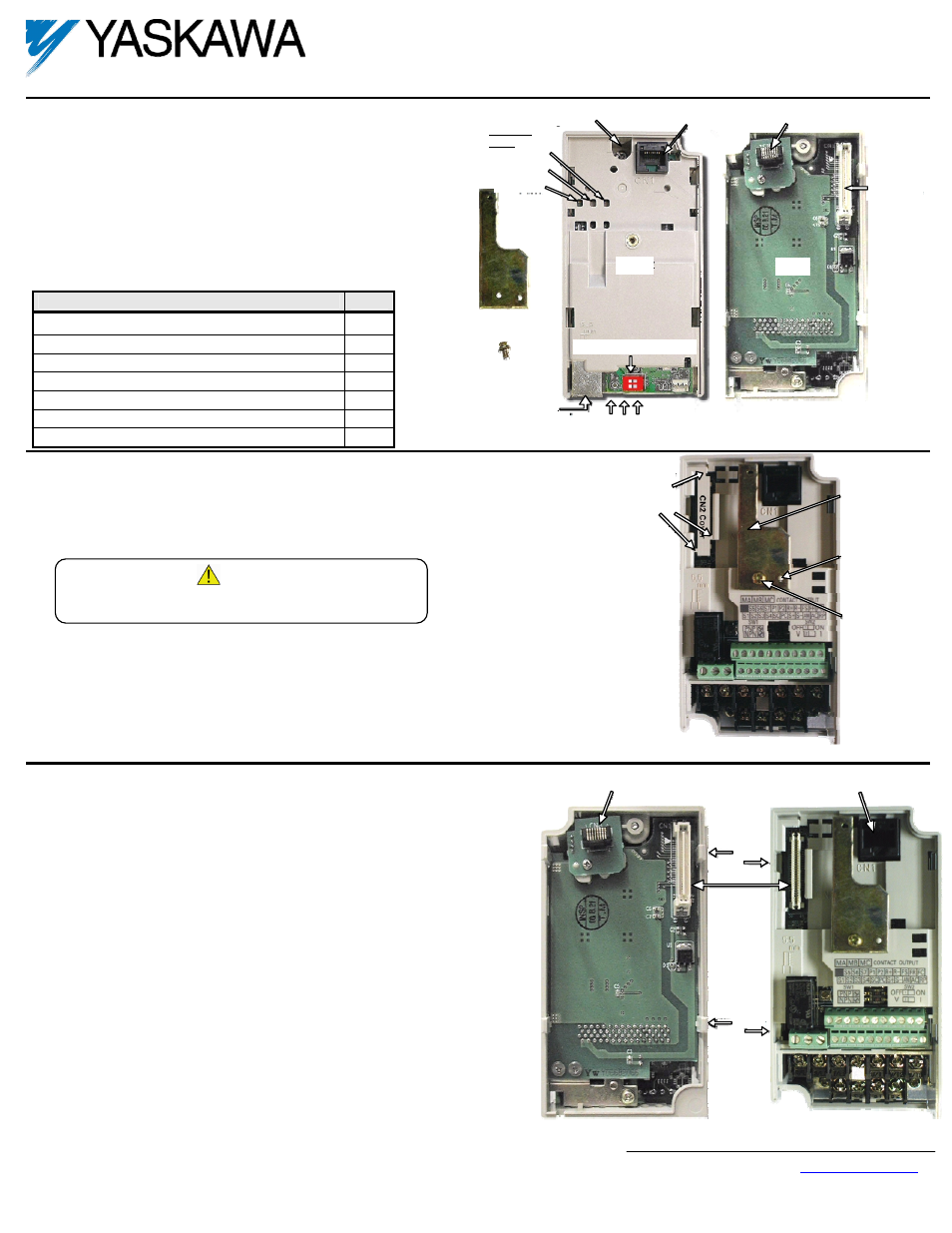
7.
Remove the CN2 cover from the V7 drive housing. Carefully snip the 3 tabs connecting the CN2
cover to the V7 housing and remove the cover.
8.
Attach the Mounting Bracket. Align the mounting bracket as shown in the figure to the right.
Secure the mounting bracket to the V7 drive housing using the M3 x 8 screw provided.
9.
Wire the V7 I/O terminals prior to mounting the V7 Modbus TCP/IP Option ring kit, as
the option will obscure power and control terminals when mounted.
10.
Mount the V7 Modbus TCP/IP Option ring kit on the V7 drive.
1. Do NOT connect a ground wire to the screw on the back of the V7 Modbus TCP/IP
Option kit.
2. Align the CN1 connector on the back of the option with its mating CN2 connector on the
front of the V7.
3. Simultaneously align connector CN3 (male RJ-45) on the back of the option with
connector CN1 (female RJ-45) on the front of the V7.
4. Align the tabs on the option with their corresponding slots on the front of the V7.
5. Press the option and the V7 drive together until the tabs lock into their associated slots.
6. Secure the option to the V7 by tightening the locking screw at the top-center of the
option.
7. Reinstall the operator keypad and all V7 covers.
Remove the CN2
protective cover by
carefully clipping the
three tabs.
Option
mounting
bracket
Align hole in the
mounting bracket
with the nib on
the front of
the V7 Drive.
Secure the
mounting bracket
to the V7 with
M3 x 8 screw.
CN1-Modular Jack
RJ-45 Female
CN3-Modular Plug
RJ-45 male
Tab
Tab
Slot
Slot
CN1 – CN2
Locking Screw
Indicator
LEDs
Mounting Bracket
M3 x 8 Screw
Cable Connector
RJ-45 Ethernet
Load Defaults Switch
CN1-Modular Plug
RJ-45 Female
CN3-Modular Plug
RJ-45 Male
CN1
Connector
NS/CON
MS/RUN
PWR
Front
Back
10/100, LINK, Rx
Ethernet LEDs
WARNING!
Dangerous voltages in excess of 400VDC (230V drives) or 800VDC
(460V drives) are present at the DC bus terminals of the drive.