Yaskawa CM091 User Manual
Page 2
Yaskawa Electric America, Inc –
www.yaskawa.com
IG.V7.25, Page 2 of 6
Date: 10/08/09, Rev: 09-10
11.
LED Descriptions
The V7 Modbus TCP/IP Option LEDs status after the power up sequence is described below.
Please wait for at least five seconds for the loading process to complete before verifying the status
of the LEDs.
LED
Description
MS/RUN GREEN – Card Functioning Normally
RED – Card Failure
NS/CON
GREEN – Connection Made
GREEN BLINK – Control Connection Active
(500ms cycle)
RED – Connection Fault
10/100 GREEN – 100MBPS Connection Speed
LINK GREEN – Link Established
Rx
GREEN - Message Received
PWR GREEN - Appropriate Power Supplied to Card
12.
Connect to the V7 Modbus TCP/IP Option card.
Note: It is strongly recommended that shielded CAT-5 cable be used.
1. Connect to the Ethernet network.
1.1. Direct connection: To connect directly to the V7 Modbus TCP/IP Option card, plug one
end of a shielded CAT-5 cross-over cable into the RJ-45 socket on the V7 Modbus
TCP/IP Option card. Connect the other end to the RJ-45 Ethernet socket on the
configuration device, typically a controller, laptop or other PC.
1.2. Connection through hub or switch: To connect through a switch, hub or router, connect
V7 Modbus TCP/IP Option card to the switch, hub or router using a standard shielded
CAT-5 patch cable.
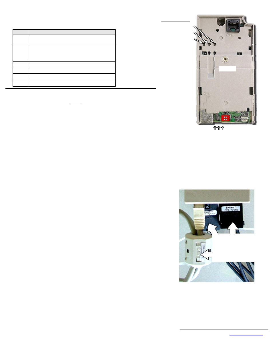
2. Loop the CAT-5 Ethernet cable through the provided ferrite (Intermark RFC-13) and
connect the ferrite as close to the RJ-45 connection as possible. Secure the ferrite to the
Ethernet cable with the provided cable tie. If the ferrite core cannot be mounted in your
installation please contact Yaskawa for application assistance. See the figure in the lower right
corner of this page.
3. Attach the provided ferrites to the V7 drive motor and power leads as close to the V7 drive
terminals as possible (typically within 1 foot). Secure the ferrites to the motor and power leads
with the provided cable ties. See the figure in the lower right corner of this page.
13.
Configure the PC Network Connection
.
1.
Select an existing connection or create a new network connection for communication with
the V7 Modbus TCP/IP Option card.
1.1. Select Start
⇒ Settings ⇒ Network Connections from the task bar in the Windows
OS.
1.2. Select the network connection to be used.
2. Right click on the network connection and select Properties from the menu.
3. Select Internet Protocol (TCP/IP) from the components displayed.
Note: If a TCP/IP selection is not available, it may be installed by selecting Install.
Administrator access to the PC and the operating system installation CD-ROM may also
be required.
3.1. Select Properties.
Note: It is very important to record the existing network setup so that the configuration
PC can be restored to its original configuration.
3.2. Select the Use the following IP address radio button.
3.3. Enter the IP address as 192.168.1.19 and the Subnet mask as 255.255.255.0. Check the
system network schematic or with your network administrator to ensure that the IP
address does not already exist on the network.
3.4. Once the IP address and Subnet mask are entered, select OK.
Note: It may be necessary to reboot the PC in order for the changes to take affect.
Ferrites around power
and motor leads.
Ferrite around looped
CAT-5 Ethernet cable.
Successful Initialization:
The V7 Modbus TCP/IP Option kit hardware is installed and
operating correctly with the LEDs in the states shown in bold
text in the “LED Descriptions” table. The LINK LED
represents the status of the physical connection to the network
and is not indicative of any card state.
Indicator LEDs
NS/CON
MS/RUN
PWR
Front
10/100, LINK, Rx
Ethernet LEDs
Application of Ferrites:
The V7 Modbus TCP/IP Option kit includes 3 ferrites which
must be mounted to the Ethernet cable, incoming power leads,
and motor leads. See Section 12, steps 2 and 3.