Smart trac cpu card layout, J5 connector pinout – Yaskawa SmartTrac CPU Card User Manual
Page 14
SMART TRAC CPU Card
10
••
Interrupts and Addresses Used by the Smart Trac CPU Card Technical Manual
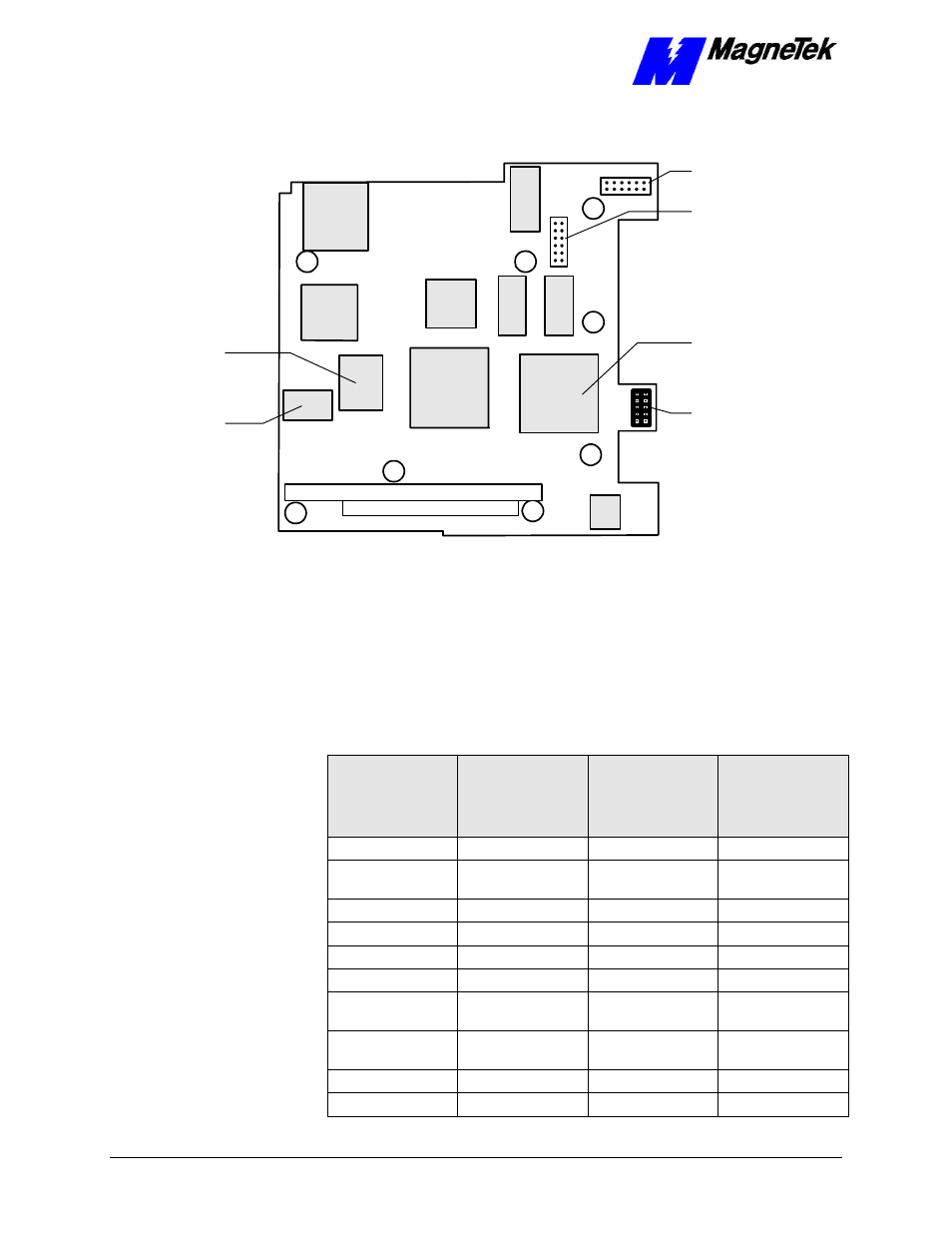
Smart Trac CPU Card Layout
PC/104 Connector
PC/104 Connector
46S03415-
0010
REV. 01 S/N 0000001
M
agneTek
Lithium
Battery
Flash ROM
CPU
J5 Connector
J4 Connector
J7 Connector
(Not Used)
Figure 2. Smart Trac CPU Card Layout.
J5 Connector Pinout
The pinout of Smart Trac CPU card connector J5 is shown in the table below.
One end of a ribbon cable plugs into J5 on the CPU card and the other end of the
cable plugs into DB9 connector on the front of the Smart Trac unit. The DB9
Connector, with only 9 pins, has no connection to the J5 pin.
Smart Trac
CPU card
connector
DB9 Pin #
Smart Trac
Unit
connector J5
Pin #
Signal
Abbreviation
Signal
Description
1
1
NC
No Connection
2
3
Tx
Transmit (from
CPU)
3
5
Rx
Receive (to CPU)
4
7
NC
No Connection
5
9
C5ISO
Common
6
2
NC
No Connection
7
4
CTS
Clear to Send (to
CPU)
8
6
RTS
Request to Send
(from CPU)
9
8
NC
No Connection
-
10
NC
No Connection