Yaskawa MP930 User Manual
Page 229
6.1 Support Functions for Controlled Axes
6 -7
The following shows parameters related to Infinite Length Positioning.
Name
Parameter No.
Setting Range
Remarks
Servo Module
Function Selection
Flag
Fixed parameter
17 b5
0, 1
0: Finite Length Mode
1: Infinite Length Mode
POSMAX
Fixed parameter
22
1 to 2
31
−1
Units: 1 = 1 reference unit
D
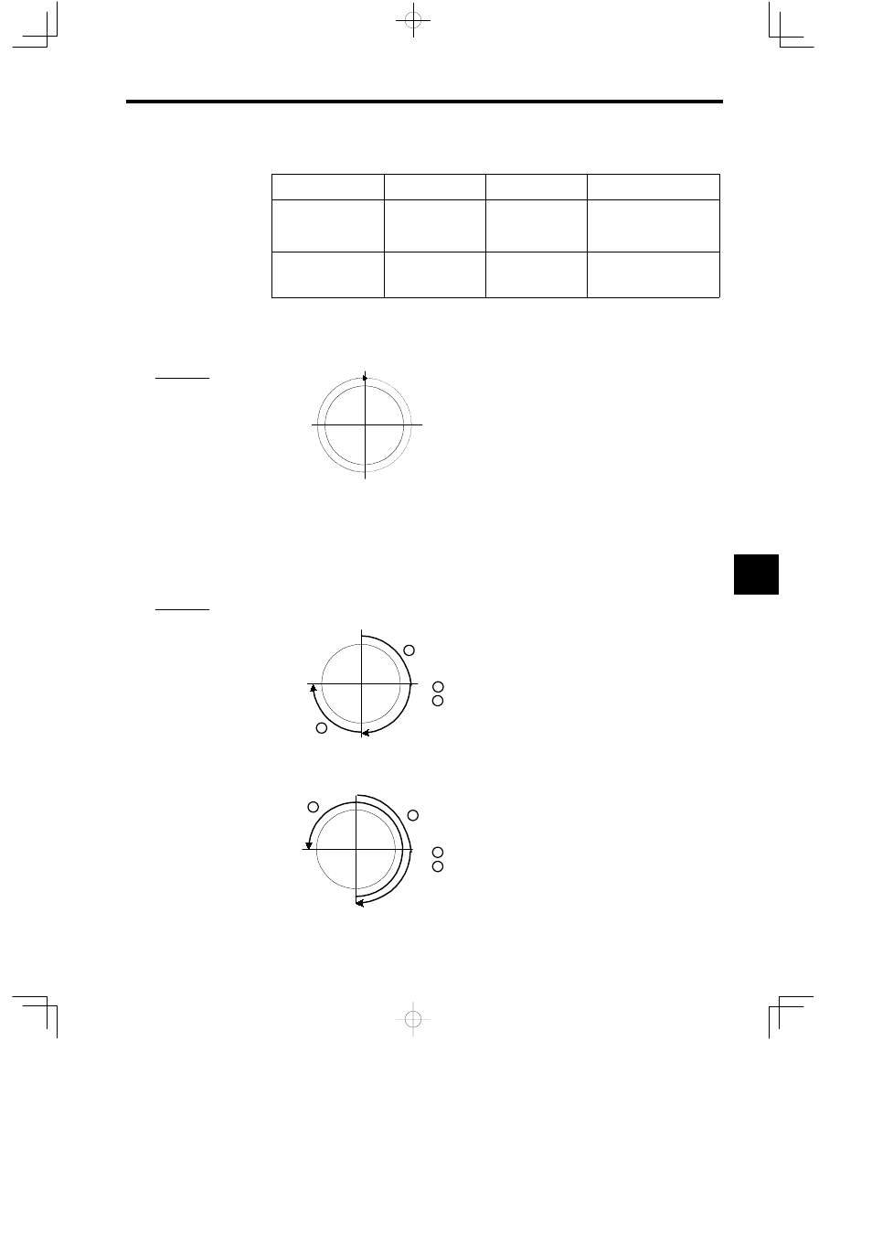
Procedure for Specifying Incremental Mode in Infinite Length Mode Axis
A relative reference can be set in Infinite Length Mode Axis at the same range as that for
Finite Length Mode Axis. (Range: −214783648 to 214783647.)
ZRN [X1] 0;
INC MOV [X1] 180.0;
INC MOV [X1] 2700.0; Move clockwise 7.5 rotations to 0°.
180°
90°
0°
270°
Figure 6.1
Specifying Incremental Mode in Infinite Length Mode Axis
D
Procedure for Specifying Absolute Mode in Infinite Length Mode Axis
Reference codes signify the direction of rotation and reference angles signify absolute
position as shown in the figure below when absolute references are set in Infinite Length
Mode Axis.
Refer to Figures 6.2 and 6.3 where the current position is specified at position 180° .
ZRN [X1] 0;
INC MOV [X1] 180.0;
ABS MOV [X1] 270.0; Turn clockwise (forward) to 270°.
180°
90°
0°
270°
1
2
1
2
Figure 6.2
Specifying Absolute Mode in Infinite Length Mode Axis (Example 1)
ZRN [X1] 0;
INC MOV [X1] 180.0;
ABS MOV [X1] −270.0; Turn counterclockwise (reversed)
to 270°.
180°
90°
0°
270°
1
2
1
2
Figure 6.3
Specifying Absolute Mode in Infinite Length Mode Axis (Example 2)
6
A
EXAMPLE
"
A
EXAMPLE
"