2 encoder orientation constants – Yaskawa Varispeed 626M5 User Manual
Page 175
Control Constants
10-8
10.2 Encoder Orientation Constants
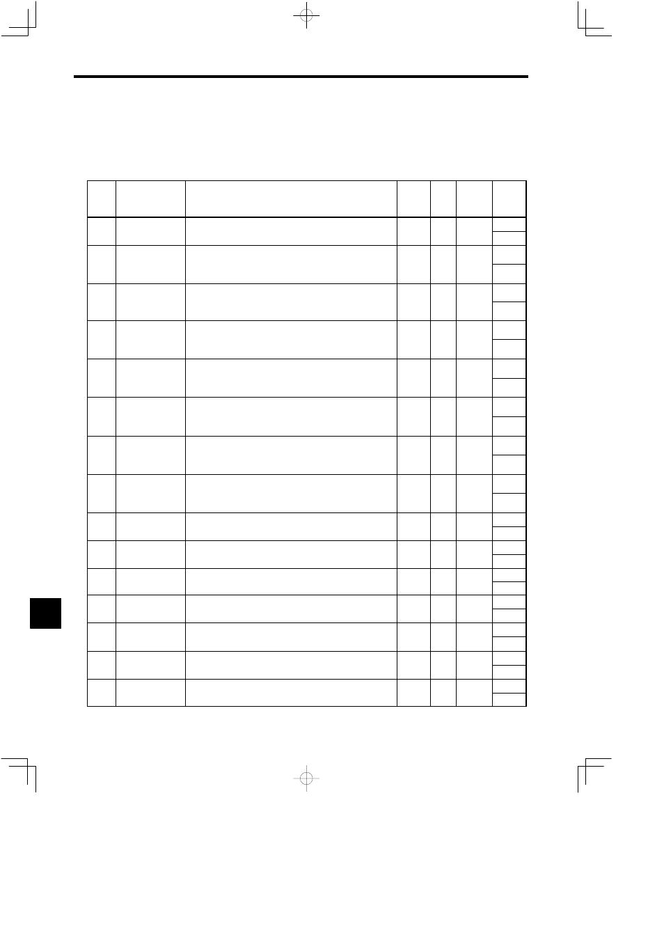
The encoder orientation constants are listed in the following table.
Table 10.2
Encoder Orientation Constants
Con-
stant
No.
Name
Explanation
Change
*
1
Unit
Standard
Setting
Upper
Limit/
Lower
Limit
C2 01
Load Shaft Position-
ing Origin
Mechanical origin of the load shaft. Set difference from encoder ori-
gin signal (phase C) pulses
Yes
Pulse
0
4095
C2-01 ing Origin
P
ORG
gin signal (phase C) pulses.
Yes
Pulse
0
0
C2 02
Position Control
Proportional Gain
(H)
Position control proportional gain when high-speed gear is selected
(i.e., MGR and LGR are OFF) or when high-speed winding is se-
l
d (i
CHW i OFF) I
i
K
i
i idi
Yes
1/s
15
99
C2-02
p
(H)
K
PH
(
,
)
g
p
g
lected (i.e., CHW is OFF). Increasing K
PH
increases rigidity.
Speed reference (pps) = K
PH
× Position tolerance (pulses)
Yes
1/s
15
1
C2 03
Position Control
Proportional Gain
Position control proportional gain when medium-speed gear is se-
lected (i.e., MGR is ON). Increasing K
PM
increases rigidity.
Yes
1/s
15
99
C2-03
Proportional Gain
(M)
K
PM
lected (i.e., MGR is ON). Increasing K
PM
increases rigidity.
Speed reference (pps) = K
PM
× Position tolerance (pulses)
Yes
1/s
15
1
C2 04
Position Control
Proportional Gain
(L)
Position control proportional gain when low-speed gear is selected
(i.e., LGR is ON) or when low-speed winding is selected (i.e., CHW
i ON) I
i
K
i
i idi
Yes
1/s
15
99
C2-04
p
(L)
K
PL
(
,
)
p
g
(
,
is ON). Increasing K
PL
increases rigidity.
Speed reference (pps) = K
PL
× Position tolerance (pulses)
Yes
1/s
15
1
C2 05
Speed Control Pro-
portional Gain (H)
K
Speed control proportional gain when high-speed gear is selected
(i.e., MGR and LGR are OFF) or when high-speed winding is se-
l
d (i
CHW i OFF) i
i
i
l (i
ORT i ON)
Yes
%/Hz
40
255
C2-05
p
( )
K
VHO
(
,
)
g
p
g
lected (i.e., CHW is OFF) in orientation control (i.e., ORT is ON).
Torque reference P = K
VHO
× Speed tolerance
Yes
%/Hz
40
1
C2 06
Speed Control Inte-
gral Time Constant
(H)
Speed control integral time constant when high-speed gear is selected
(i.e., MGR and LGR are OFF) or when high-speed winding is se-
l
d (i
CHW i OFF) i
i
i
l (i
ORT i ON)
Yes
ms
100
1000
C2-06
g
(H)
τ
VHO
(
,
)
g
p
g
lected (i.e., CHW is OFF) in orientation control (i.e., ORT is ON).
Torque reference I = Torque reference P × Time/τ
VHO
Yes
ms
100
5
C2 07
Speed Control Pro-
portional Gain (M,
L)
Speed control proportional gain when low-speed gear is selected (i.e.,
MGR or LGR is ON) or when high-speed winding is selected (i.e.,
CHW i ON) i
i
i
l (i
ORT i ON)
Yes
%/Hz
40
255
C2-07
p
( ,
L)
K
VLO
)
g
p
g
(
,
CHW is ON) in orientation control (i.e., ORT is ON).
Torque reference P = K
VLO
× Speed tolerance
Yes
%/Hz
40
1
C2 08
Speed Control Inte-
gral Time Constant
(M L)
Speed control integral time constant when low-speed gear is selected
(i.e., MGR or LGR is ON) or when low-speed winding is selected
(i
CHW i ON) i
i
i
l (i
ORT i ON)
Yes
ms
100
1000
C2-08
g
(M, L)
τ
VLO
(
,
)
p
g
(i.e., CHW is ON) in orientation control (i.e., ORT is ON).
Torque reference I = Torque reference P × Time/τ
VLO
Yes
ms
100
5
C2 09
Positioning Comple-
tion Detection Width
Detection width for outputting completion signal when the load shaft
approaches the stop reference position Detection width is stop refer
No
Pulse
5
200
C2-09 tion Detection Width
Z
FIN
approaches the stop reference position. Detection width is stop refer-
ence position ±Z
FIN.
No
Pulse
5
0
C2 10
Positioning Comple-
tion Cancel Width
Set value for canceling completion signal when the load shaft is
moved after completion signal is output Cancel width is stop refer
No
Pulse
10
200
C2-10 tion Cancel Width
Z
CAN
moved after completion signal is output. Cancel width is stop refer-
ence position ±Z
CAN.
No
Pulse
10
Z
FIN
C2 11
Orientation Speed
S
Speed applied (after detecting encoder origin) until changing to the
servo loop during orientation
No
min
−1
400
600
C2-11 S
ORT
servo loop during orientation.
No
min
−1
400
40
C2 12
BCD Stop Position
Reference Resolu
Angle set value per minimum increment of stop position BCD com-
mand
No
Deg
1 0
180.0
C2-12 Reference Resolu-
tion P
BCD
mand.
No
Deg.
1.0
0.5
C2 13
Virtual Stop
Position Offset
Stop position offset for smoothing stop operation when the servo loop
is used When Z
FIN
is reached offset becomes 0
No
Pulse
0
100
C2-13 Position Offset
P
IMG
is used. When Z
FIN
is reached, offset becomes 0.
No
Pulse
0
0
C2 14
Orientation Speed
Changing Ratio
Speed changing ratio for gradually reducing orientation speed to
reduce gear noise when switching from orientation speed to servo
No
0
100
C2-14 Changing Ratio
R
SOR
reduce gear noise when switching from orientation speed to servo
loop speed.
No
---
0
0
C2 15
Starting Soft Start
Time
Soft start time for accelerating from at rest state to orientation speed.
Use this parameter to reduce gear noise at starting Acceleration rate
No
ms
0
50
C2-15 Time
T
SFO
Use this parameter to reduce gear noise at starting. Acceleration rate
is (500 min
−1
)/sec.
No
ms
0
0
10