2 connection diagram – Yaskawa Varispeed 626M5 User Manual
Page 45
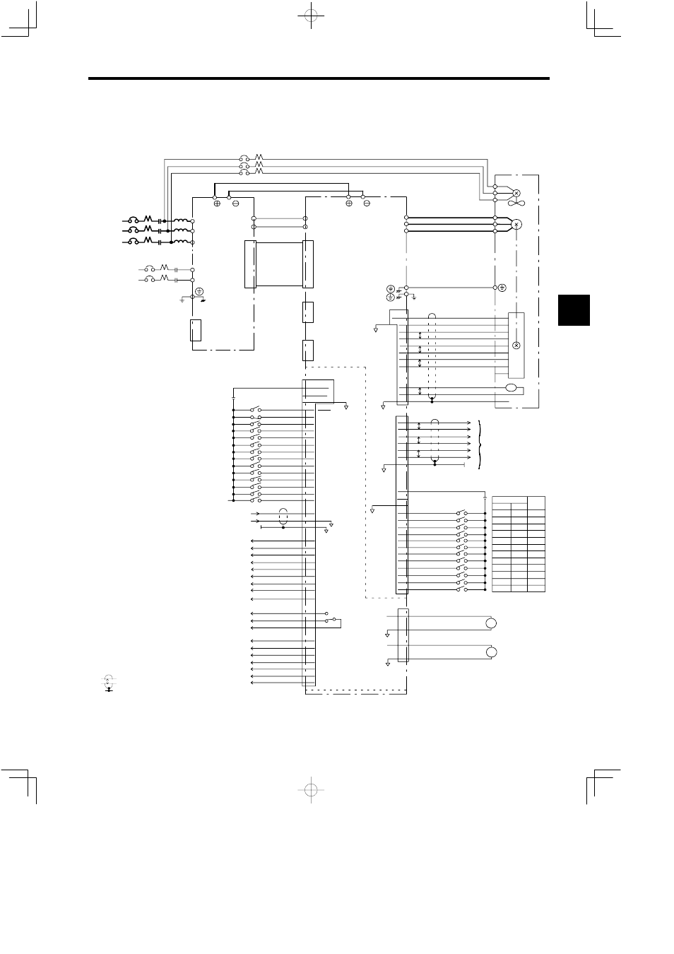
3.2 Connection Diagram
3 -5
3.2 Connection Diagram
The connection diagram of the Inverter and Converter is shown in Figures 3.3 and 3.4. Figure 3.3 is for a M5A
Inverter model for stand-alone drives and Figure 3.4 is for a M5N model for NC systems.
3MCCB
R
S
T
1MCCB 1MC
L
P/
N/
VS−656MR5
R/L1
S/L2
T/L3
P1
N1
5CN
P1
N1
51CN
VS−626M5
r
t
2MCCB
2MC
A1/r
A2/t
1CN
P/
N/
3CN
52CN
U
V
IM
2CN
+5V
0V
4,5,6
1,2,3
THSA
THSB
SS
8
7
9
1
2
3
4
5
6
7
8
9
11
12
10
PG
TS
P
PA
*PA
PB
*PB
PC
*PC
16
17
18
19
14
15
P
P
P
PAO
*PAO
PBO
*PBO
PCO
*PCO
13
14
15
16
11
12
P
P
P
SS 17
1CN
TLL(INC)
SSC(SV)
19,20,21
22,23
24,25
EXTCOM0
24VCOM
0VCOM
6CN
6
7
8
9
10
11
12
RDY
EMG
FWD
REV
TLH
13
14
5
15
16
17
18
RST
CHW
DAS
PPI
ORT
LGR
MGR
3
4
2
33
34
35
SCOM
0V
SS
ZSPD
36
37
38
39
40
46
41
TDET
TLE
ORG
ORE
CHWE
TALM
FLTL
SDET
AGR
42 COM1
43
44
45
FLT
26
27
28
29
FC0
FC1
FC2
FC3
30 COM2
BCD
BIN
1
1
2
2
4
4
8
8
1
2
4
8
U/T1
V/T2
W/T3
W
Z1
Z2
Z3
10
20
40
80
100
200
400
800
10
20
40
80
−
16
32
64
128
256
512
1024
2048
EXTCOM
24VCOM
0VCOM
D1
D2
D3
D4
D5
D6
D7
D8
D9
D10
D11
D12
33
31
32
19
20
21
22
23
24
25
26
27
28
29
30
6CN
SM
0V
0V
LM
47
48
49
50
SM
LM
3−Phase
200 VAC
*1
Single−phase
200 VAC
Ground
(100 Ω or less)
Not used
MCCB: Molded−case Circuit Breaker
MC:
Magnetic Contactor
L:
AC Reactor
External 24 V
Power Supply
*3
Speed reference
P1N1 Power Cable
Flat Cable
Not used
Digital
Operator
(Option)
*2
*2
Connection Bus Bar
Ground
(100 Ω or less)
3−Phase
200 VAC
*1
External 24 V
Power Supply
12−bit Digital Command
*3
Motor encoder
signal outputs
Motor
Cooling Fan
3rd digit 2nd digit
I/O Card
*2
EXTCOM0 of 1CN and EXTCOM are internally
isolated.
indicates shielded twisted-pair wires.
P
−
−
−
*3
For 400 V class, 3-phase 400 VAC is used.
*
1
Connection when the sequence input common
is the external common.
Fig 3.3
Connection Diagram for Stand-alone Drive, 200 V Class External Heatsink Cool-
ing Type
3