Yaskawa Sigma-5 User Manual: Design and Maintenance - Rotary Motors - Analog Voltage and Pulse Train Reference User Manual
Page 374
10.3 Troubleshooting Malfunction Based on Operation and Conditions of the Servomotor
10-27
10
Trou
blesh
ooting
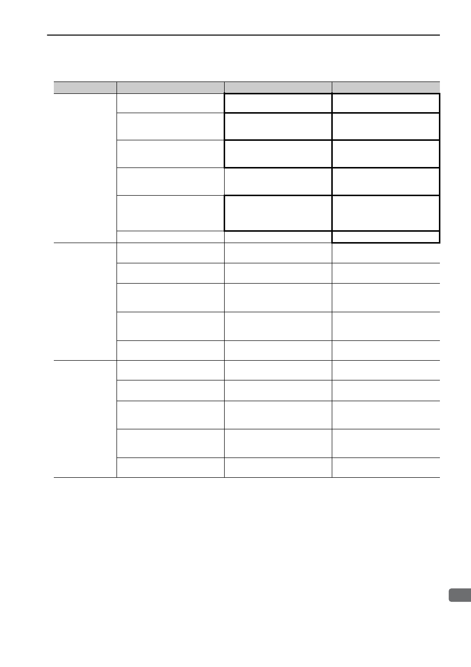
Abnormal Noise
from Servomotor
(cont’d)
Noise interference due to damaged
encoder cable.
Check if the encoder cable is bent
and the sheath is damaged.
Replace the encoder cable and cor-
rect the cable layout.
Excessive noise to the encoder
cable.
Check if the encoder cable is bun-
dled with a high-current line or near
a high-current line.
Correct the cable layout so that no
surge is applied.
The FG potential varies because of
influence from machines on the ser-
vomotor side, such as the welder.
Check if the machines are correctly
grounded.
Properly ground the machines to
separate from the encoder FG.
SERVOPACK pulse counting error
due to noise interference
Check if there is noise interference
on the I/O signal line from the
encoder.
Take measures against noise in the
encoder wiring.
Excessive vibration and shock to
the encoder
Check if vibration from the machine
occurred or servomotor installation
is incorrect (mounting surface accu-
racy, fixing, alignment, etc.).
Reduce vibration from the machine,
or secure the servomotor installa-
tion.
An encoder fault occurred.
−
Replace the servomotor.
Servomotor Vi-
brates at Fre-
quency of Approx.
200 to 400 Hz.
Unbalanced servo gains
Check to see if the servo gains have
been correctly adjusted.
Execute the advanced autotuning.
Speed loop gain value (Pn100) too
high.
Check the speed loop gain (Pn100).
Factory setting: Kv = 40.0 Hz
Reduce the speed loop gain
(Pn100).
Position loop gain value (Pn102)
too high.
Check the position loop gain
(Pn102).
Factory setting: Kp = 40.0/s
Reduce the position loop gain
(Pn102).
Incorrect speed loop integral time
constant (Pn101)
Check the speed loop integral time
constant (Pn101).
Factory setting: Ti = 20.0 ms
Correct the speed loop integral time
constant (Pn101).
Incorrect moment of inertia ratio
(Pn103)
Check the moment of inertia ratio
(Pn103).
Correct the moment of inertia ratio
(Pn103).
High Motor Speed
Overshoot on
Starting and Stop-
ping
Unbalanced servo gains
Check to see if the servo gains have
been correctly adjusted.
Execute the advanced autotuning.
Speed loop gain value (Pn100) too
high
Check the speed loop gain (Pn100).
Factory setting: Kv = 40.0 Hz
Reduce the speed loop gain
(Pn100).
Position loop gain value (Pn102)
too high
Check the position loop gain
(Pn102).
Factory setting: Kp = 40.0/s
Reduce the position loop gain
(Pn102).
Incorrect speed loop integral time
constant (Pn101)
Check the speed loop integral time
constant (Pn101).
Factory setting: Ti = 20.0 ms
Correct the speed loop integral time
constant (Pn101).
Incorrect moment of inertia ratio
data (Pn103)
Check the moment of inertia ratio
(Pn103).
Correct the moment of inertia ratio
(Pn103).
(cont’d)
Problem
Probable Cause
Investigative Actions
Corrective Actions