Valve seats, Start-up, Maintenance – Jordan Valve Mark 70 Series – Sliding Gate Control Valve User Manual
Page 2
Valve Seats
DISASSEMBLY
A.
The valve seats in all Jordan regulators are lapped to
light band flatness. Maintaining such tolerances is of
paramount importance for your assurance of excel-
lent control and tight shut-off. DO NOT use metallic
objects in removing the seats. Care in handling is
imperative.
Close the shutoff valve on each side of the valve,
1.
and remove valve from line.
Note scribed “<” on the side of the valve body (1)
2.
and cap (2). Secure the body outlet flat in a vise.
Remove the cap screws and two nuts, and lift the
cap straight up.
Before removing, check the disc (5) for a stamped
3.
arrow. This arrow points to the “<” on the body. Re-
move the disc guide and the disc. Place the valve
disc on the bench with lapped surface facing up.
Protect the lapped surfaced on both sides of the
disc guide.
IMPROPER HANDLING OF SEATS WILL RESULT
IN LEAKAGE OR POOR CONTROL.
It is imperative that the disc pin not be rotated when
disassembling, cleaning, or reassembling, since this
affects the stroke adjustment.
Lightly tap on the body to remove the plate (4).
4.
Invert the body, let valve plate drop out into your
hand, and place it on the bench with lapped sur-
face facing up.
Clean all the parts, body, and cap with solvent.
5.
Place a piece of 4/0 polishing cloth or jewelers
cloth on a smooth, flat surface such as a surface
plate, and polish the disc, plate, and disc guide
lapped seating surfaces using a “figure 8” motion.
If the parts are scarred, do not attempt to re-lap
them, but return them to the factory for repair and
replacement. If the seats are not scarred deeply,
they can be repaired at nominal cost.
The vertical sections of the disc guide serve as
6.
guides for the disc while stroking. A 0.005” feeler
gauge should be used to check for clearance be-
tween this surface and the side of the disc. If the
clearance is less, clean the guide surfaces in the
disc guide with a fine file.
B. REASSEMBLY
Place the plate in the body, lapped surface facing
1.
the cap. The index pin hole should be on the same
side as the “<” on the body. Align the disc pin so
that it is centered in the body bore and protrudes
though the center slot in the valve plate (unless you
Start-Up
Be sure that the action of the control valve and of
1.
the controller are such as to give the desired re-
sults.
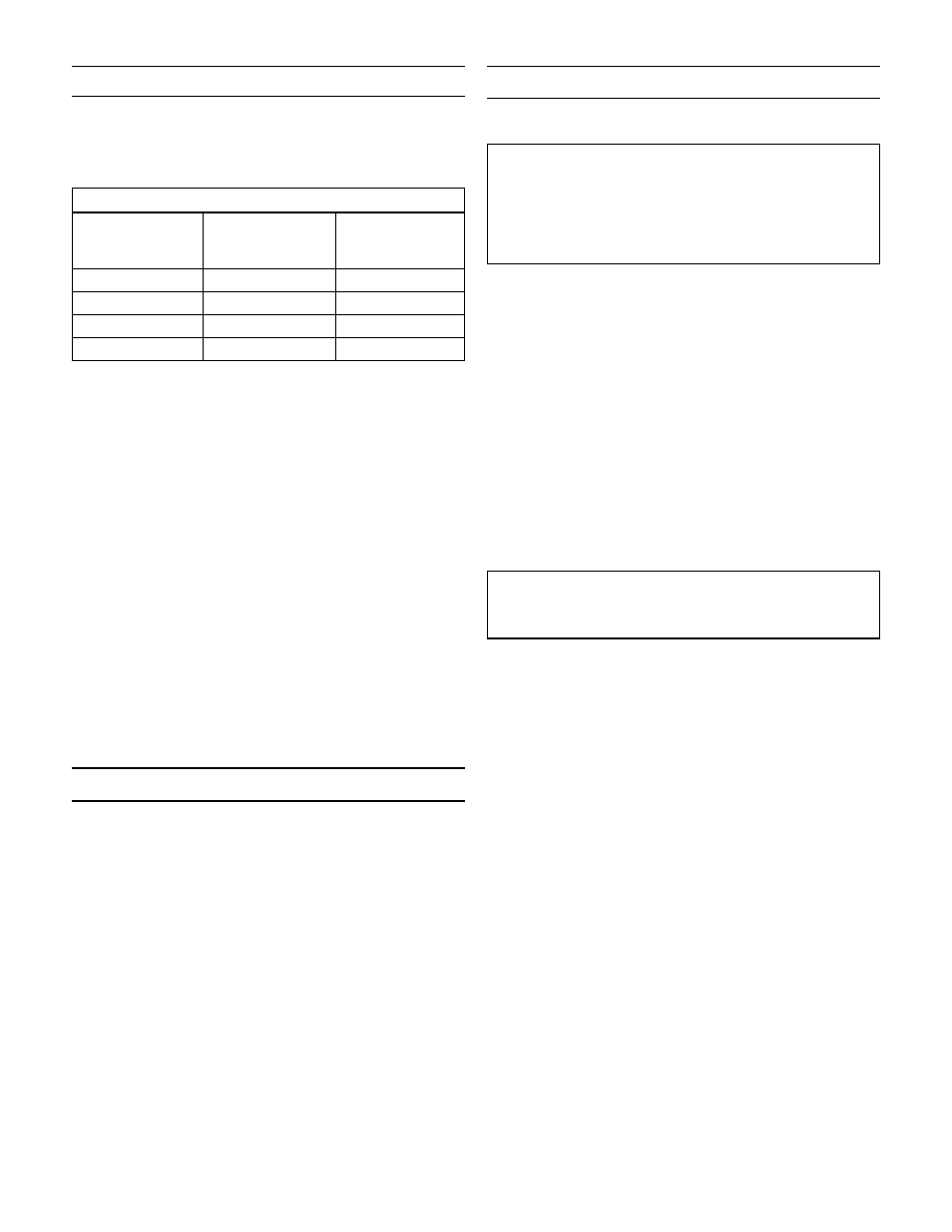
CONTROLLER ACTION
Increase in
pressure or
temperature must:
And the action of
the valve is:
Then the action
of the controller
must be:
Close Valve
Air to Close
Direct
Close Valve
Air to Open
Reverse
Open Valve
Air to Close
Reverse
Open Valve
Air to Open
Direct
The control valve has been pre-set by Jordan Valve.
2.
However, finer adjustments may be required to
compensate for pressure drop conditions of the
application. Do not apply more than 45 psi to the
actuator.
With the inlet, outlet, and by-pass shut-off valves
3.
closed, and no pressure in the downstream line,
fully open the outlet shutoff valve. Slowly open the
inlet valve just enough to start flow through the
control valve. Increase flow gradually by slowly
opening the inlet shut-off valve. Do not fully open
the inlet valve until you are sure that the controller
and control valve have control of the system. Usu-
ally, the handwheel on the inlet valve will turn freely
when this point is reached.
To shut off the line fluid, close the inlet shut-off
4.
valve first, then the outlet shut-off valve.
Body and cap bolts should be retightened per
5.
torque procedures after valve reaches operating
temperature.
Maintenance
Caution: Make certain that there is no pressure in the
valve before loosening any fittings or joints. The fol-
lowing steps are recommended:
Close inlet shutoff valve.
1.
Allow pressure to bleed off through downstream
2.
piping. Do not attempt to reverse the valve by
bleeding pressure from the upstream side of the
valve.
When the pressure gauges indicate that all pres-
3.
sure has been removed from the system, close the
outlet shutoff valve, and the valve may be serviced.
Note: refer to the drawing at the end of this document
for description and proper orientation of parts.
-2-