Jordan Valve Mark 79/79MX Series – 3 Way Mixing/Diverting Valve User Manual
I & m mark 79/79mx, Ideal installation, Start up
3170 Wasson Road • Cincinnati, OH 45209 USA
Phone 513-533-5600 • Fax 513-871-0105
[email protected] • www.jordanvalve.com
I & M Mark 79/79MX
Installation & Maintenance Instructions for
Mark 79 Three Way Control Valves (1/4” - 2”)
Warning: Jordan Valve Control Valves must only be used, installed and repaired in accordance with these Installa-
tion & Maintenance Instructions. Observe all applicable public and company codes and regulations. In the event
of leakage or other malfunction, call a qualified service person; continued operation may cause system failure or a
general hazard. Before servicing any valve, disconnect, shut off, or bypass all pressurized fluid. Before disassembling
a valve, be sure to release all spring tension.
Please read these instructions carefully!
Your Jordan Valve product will provide you with long,
trouble-free service if it is correctly installed and main-
tained. Spending a few minutes now reading these in-
structions can save hours of trouble and downtime later.
When making repairs, use only genuine Jordan Valve
parts, available for immediate shipment from the factory.
Ideal Installation
To protect the valve from grit, scale, thread chips
1.
and other foreign matter, ALL pipelines and piping
components should be blown out and thoroughly
cleaned before the installation process begins.
Shutoff valves, pressure gauges and by-pass piping
2.
should be installed as indicated in the Ideal Installa-
tion Schematic to provide easier adjustment, opera-
tion, and testing.
In preparing threaded pipe connections, care
3.
should be exercised to prevent pipe-sealing com-
pound from getting into the pipe lines. Pipe seal-
ing compound should be used sparingly, on male
threads only, leaving the two lead threads clean.
Jordan uses and recommends Seyco #2415 thread
sealer Teflon ribbon.
A line strainer should be installed on the inlet side
4.
of the valve. A 0.033 perforated screen is usually
suitable. Line strainers are available from Jordan
Valve.
Install the valve in the highest horizontal line of
5.
piping to provide drainage for inlet and outlet pip-
ing, to prevent water hammer and to obtain faster
response.
The flow arrow on the valve body must be pointed
6.
in the direction of flow. The valve may be installed
vertically or horizontally without affecting its opera-
tion.
For best control, 3’ 0” straight sections of pipe
7.
should be installed on either side of the valve.
In hot vapor lines, upstream and downstream pip-
8.
ing near the valve should be insulated to minimize
condensation.
If possible, install a relief valve downstream from
9.
the valve. Set at 15 psi above the control point of
the valve.
Expand the outlet piping at least one pipe size if
10.
the controlled pressure (downstream) is 25% of
the inlet pressure or less. A standard tapered ex-
pander connected to the outlet of the valve is rec-
ommended.
Where surges are severe, a piping accumulator is
11.
recommended.
The air piping or tubing to the diaphragm case
12.
should be 1/4” or 3/8”. The length of tubing should
be less than 150 feet.
Start Up
The MK79 Control Valve has been pre-set by
1.
Jordan; however, finer adjustments may be
required to compensate for pressure drops of
the application. See the “Spring Pre-Loaded
Adjustment” section.
Close all inlet, outlet and by-pass shut-off valves.
2.
Remove all pressure from downstream lines.
Fully open the outlet shut-off valves. Slowly open
3.
the inlet shut-off valve just enough to start flow
through the control valve. Increase the flow
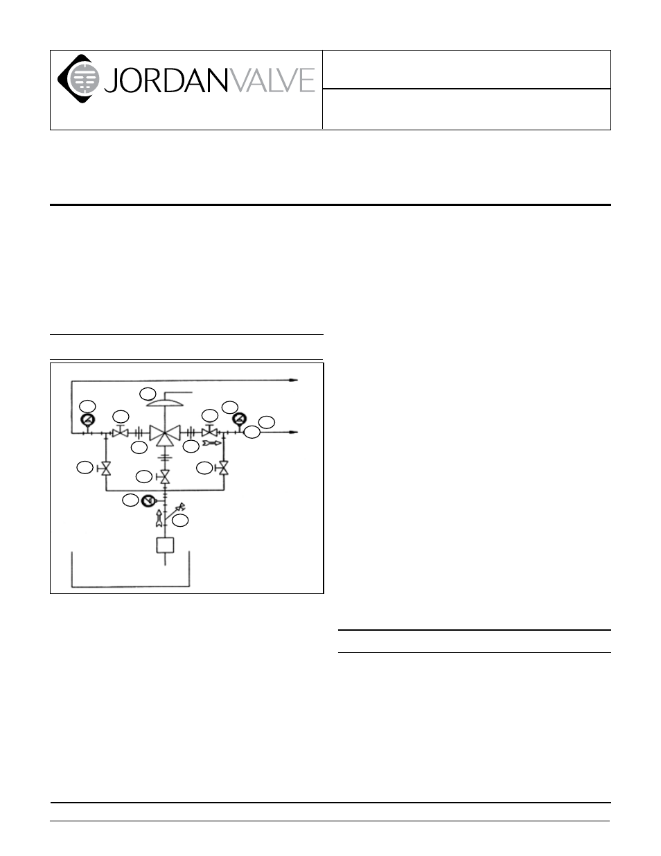
Main Line
Control Valve
1. Shut off Valve
2. Pipe Union
3. Strainer and Drain Valve
4. Pressure Gauge
5. Jordan Series 790 DCV
6. Relief Valve
Pump
Reservoir
4
R
6
4
1
5
1
1
2
2
1
1
4
3
PROTECT VALVES WITH LINE STRAINERS