Jordan Valve 657M Series Diaphragm Actuator User Manual
Page 3
-3-
vi.
Ensure that the desired total
travel is available by cycling the
actuator. This will also
demonstrate that the valve
plug seats properly. If
necessary,
minor
travel
adjustments can be made
by slightly loosening the stem
connecter,
tightening
the
locknuts and screwing the
stem either into or out of the
stem connecter using a wrench
on
the
locknuts.
vii.
Once the valve travel has been
accomplished,
secure
the stem connector, lock
the travel indicator disc
against
the
connector
using the locknuts, and
adjust the travel indicator scale
(key 16) to show
valve
plug
position.
viii.
Using a gauge, measure the
pressure
delivered
to
the actuator. Make any
adjustments on the actuator, or
the
positioner,
to set the starting point of
valve
travel
and
ensure
full range of travel as desired.
b.
Mounted on Body with “Push Down to
Open” Valve Plug
i.
Attach the locknuts to the stem
and set the travel indicator disc
into
position.
ii.
Raise the valve plug to the
closed position. On larger body
sizes, a pry bar may be inserted
through the body line flange
opening. If the valve is located
in a pipeline application,
you
may
remove
the bottom flange and raise the
valve plug from below.
iii.
Install the stem connector and
ensure that the actuator
stem threads are fully engaged.
iv.
Install the two cap screws in the
stem connector to clamp the
actuator stem to the valve stem.
v.
If a pry bar has been used,
remove it now. If the
bottom flange has been
removed, replace it now.
vi.
Apply loading pressure to the
diaphragm case and move the
valve plug down off of its seat.
vii.
Rotate the valve plug stem into
the
stem
connector
approximately 1/8”. Slightly
tighten
the
stem
lock
nuts to move the travel indicator
to the proper position.
viii.
Check the availability of desired
travel by fully cycling the actua-
tor. The valve plug should seat
before the upper travel stop. If
required, minor adjustments to
total travel can be made
by slightly loosening the
stem connector, tightening the
locknuts and screwing the stem
either into or out
of the stem connector
using a wrench on the locknuts.
Note: When making adjustments to the valve stem,
do not rotate the valve stem more than the 1/8” that it
was screwed into the actuator stem in step “vii”. Over
rotating the valve stem will prevent the valve from
shutting off.
ix.
Proceed with steps “vii” and
“viii” as in section “A” above.
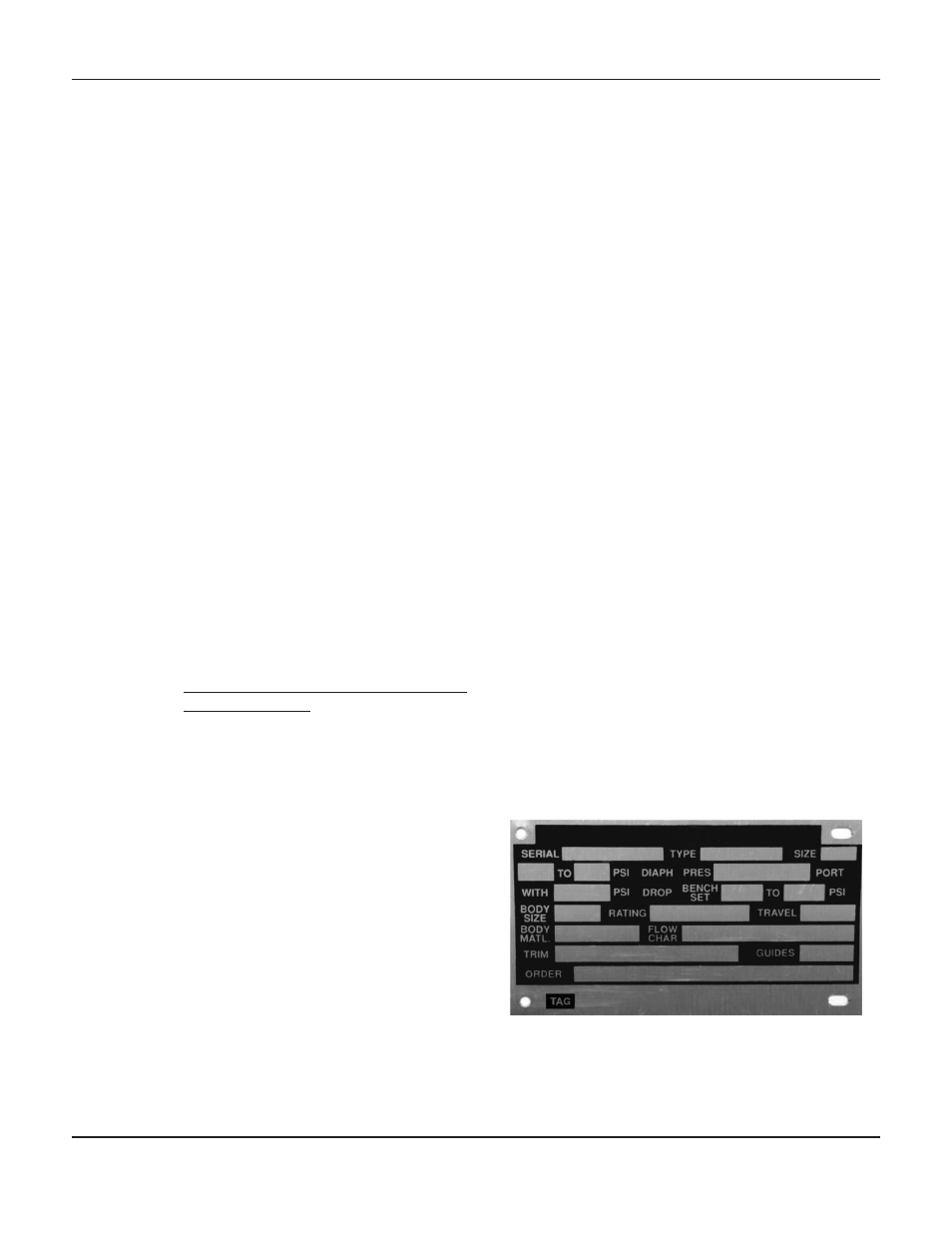
Serial Number
Each 657M Actuator has a serial number, stamped on
the nameplate. When corresponding with your Jordan
Valve representative, always refer to that serial number
when requiring replacement parts or technical informa-
tion.
Figure 2: Nameplate on 657M Actuator
657M S
erieS
D
iaphragM
a
ctuator