Jordan Valve 1051M Series Rotary Actuator User Manual
Page 8
-8-
Changing Actuator Mounting Continued,
3.
If changing styles,
a.
Remove the cap screws (Key 32) and
the actuator housing (Key 17) from the
mounting yoke (Key 35).
b.
Rotate the housing 180 degrees while
maintaining the appropriate position (1,
2, 3 or 4) and place the actuator
onto the mounting yoke (Key 35).
4.
If changing positions, remove cap screws (Key
32) and rotate the actuator housing to
the desired position.
Note: Consult Table 1 for appropriate bolt torques.
5.
Secure the actuator housing (Key 17) to the
mounting yoke (Key 35) with cap screws
(Key 32).
6.
Refer to the appropriate valve body instruction
manual for lever/valve shaft orientation
marks and slide the lever into
place. Consult Figure 4 for lever operat
ing clearance. Clamp with the cap screw (Key
10).
7.
Rotate the lever (Key 33) to align with the rod
end bearing (Key 13). This connection
can be aided by stroking the actuator slightly off
its up travel stop with a regulated air source.
8.
Apply thread locking compound to the threads
of the cap screw (Key 12).
9.
Connect the lever (Key 33) and the rod end
bearing (Key 13) using the cap screw and hex
nuts (Keys 12 and 31). This connection
can be aided by stroking the actuator slightly off
its up travel stop with a regulated air source.
Note: Tighten cap screw (Key 12) to the recommend-
ed bolt torque shown in Table 1.
10.
Position the travel indicator (Key 38) according
to the valve position and direction of rotation.
11.
Replace the cover (Key 41) and secure it with
cap screws and washers (Keys 8 and 9). If
the holes in the cover and housing (Key
17) do not align, use a regulated air
source to move the actuator slightly
off its up travelstop. If this does not
result in proper alignment, temporarily
loosen the cap screws (Key 32)
and shift the housing slightly. Do not stroke the
actuator while the cover is off.
12.
Refer to the Adjustment section of this manual
for correct actuator turnbuckle adjustment.
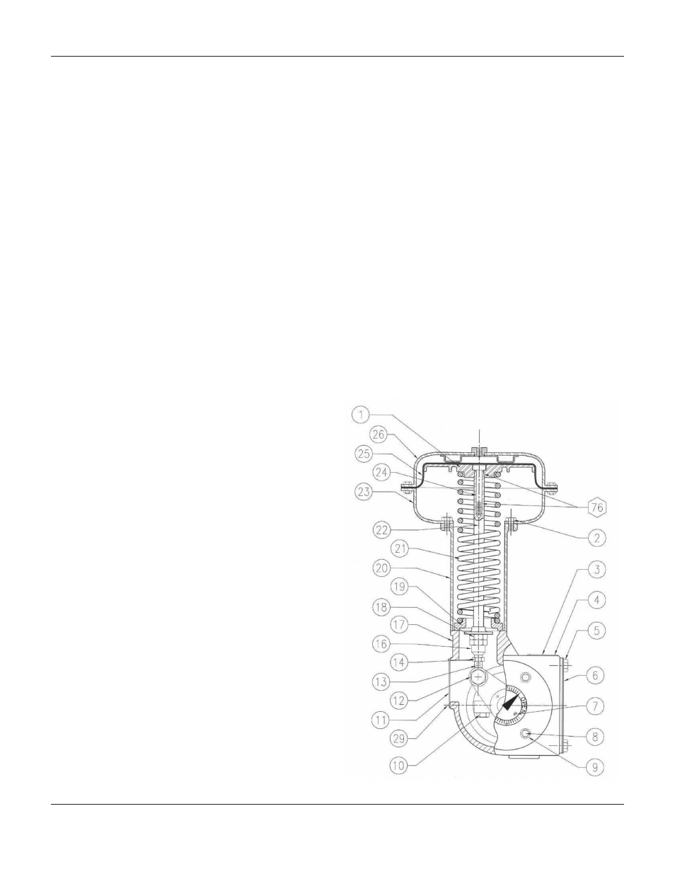
Parts Ordering
The serial number for your 1051M Rotary Actuator is
located on the nameplate (Figure 1 and Key 3, Figure 6).
Please refer to your serial number when corresponding
with your Jordan Valve representative. When ordering
replacement parts, please refer to the following parts list.
Figure 6:
Typical 1051M
Actuator
Assembly
1051M S
erieS
r
otary
a
ctuator