Motherboard layout, Chapter 3, Motherboard information – Lanner MR-320 User Manual
Page 11
Advertising
8
Motherboard Information
Chapter 3
Network Application Platforms
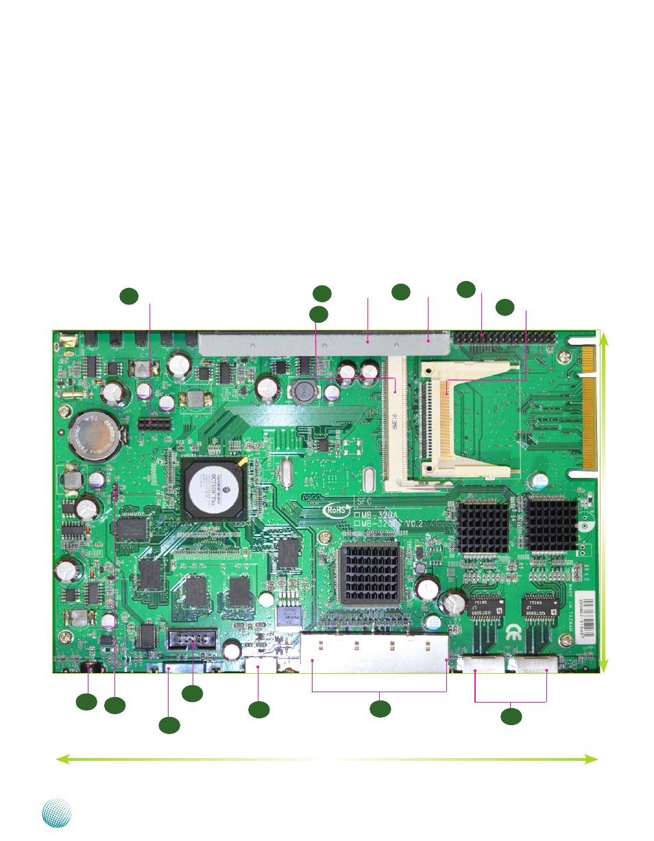
Motherboard Layout
The motherboard layout shows the connectors and
jumpers on the board. Refer to the following picture
as a reference of the pin assignments and the internal
connectors.
NetROM Downloader (P3)
USB Interface
Connector (JP2)
Ethernet Ports (P5)
USB2.0 Ports (P4)
JP1: Flash Mode
Selector (JP1)
External Serial Port (P3)
Internal Serial Port (JP6)
B o o t l o a d e r M o d e
Jumper
M7
JTag(JP4)
CompactFlash Connector
(P1)
Mini-PCI Connector (PX1)
M1
M2
M3
M4
M5
M6
M8
M9
M10
M11
M12
218mm
146mm
WAN Ports (P6, P7)
M13
Reset Switch (Sw1)
Advertising