Chapter 3, Chapter 3: board layout, Board layout – Lanner LEC-6020 User Manual
Page 11: External connectors
Advertising
11
Board Layout
Chapter 3
Embedded and Industrial Computing
Chapter 3:
Board Layout
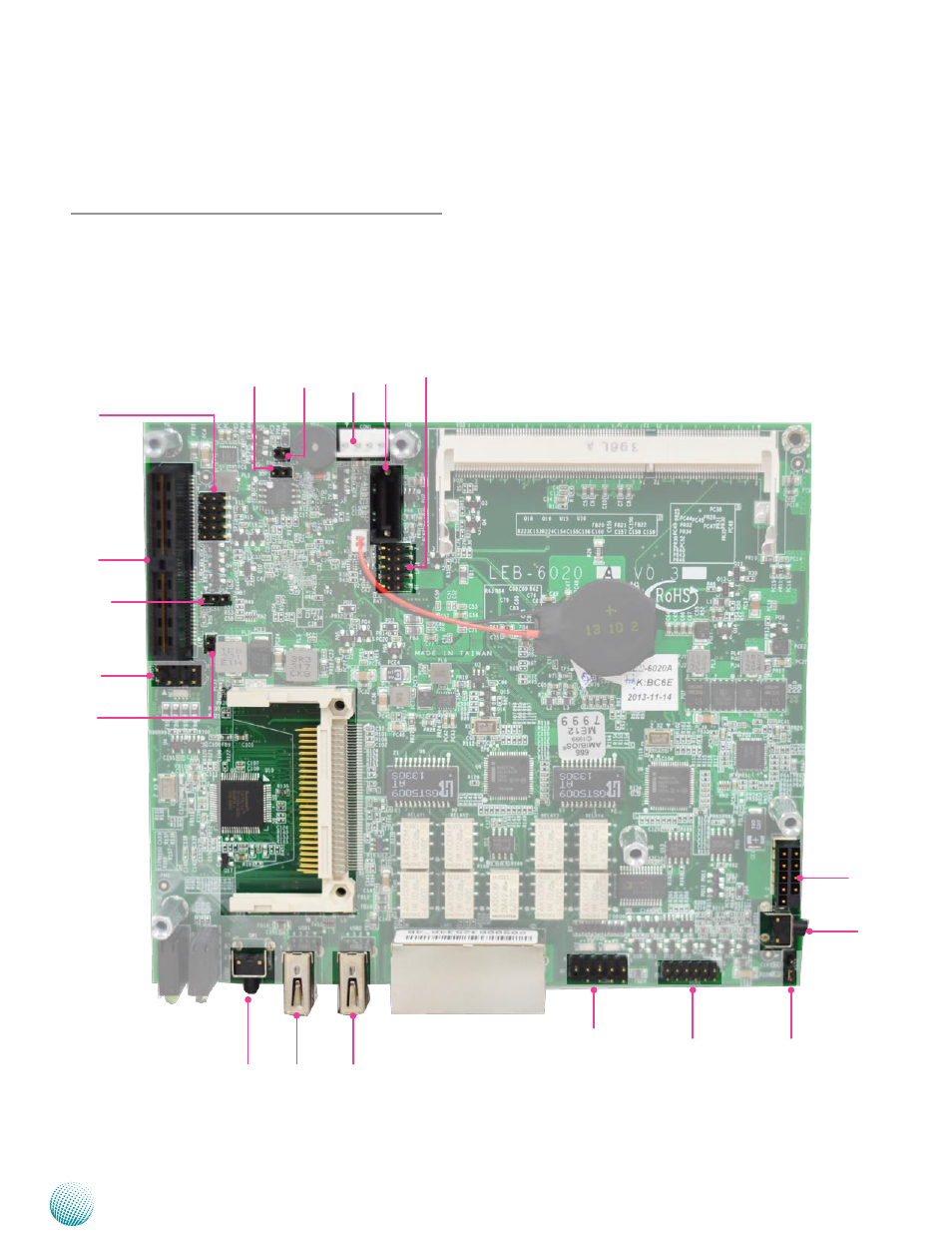
External Connectors
The following picture highlights the location of system
jumper settings and connectors of the LEC-6020 main
board. Refer to the table 3.1 Connector List for more
details.
USB1
USB2
SW1
COM1
VGA1
RST2
RST1
JP1
LPC1
SATA1
CON1
BWP1
CLR1
SPI2
J3
SMB1
KBMS1
PWR1
Advertising