Jumper settings, Chapter 3, Board layout – Lanner LEC-7230 User Manual
Page 13: Jri1 : com1 jri2 : com2
13
Board Layout
Chapter 3
Embedded and Industrial Computing
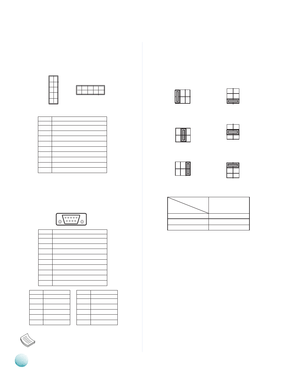
Select COM1/COM2 Pin 9 Function (JRI1/JRI2): The
pin 9 of COM1 and COM2 can be altered by JRI1 and JRI2
respectively according to the following jumper settings.
Default
+5V
+12V
Jumper Setting
Function
SW1/SW4
RI# (default)
1-2
+5V
3-4
+12V
5-6
Jumper Settings
RS-232 Pin Headers (JCOM1/2): It is a RS-232 serial
communication interface Connector
RS-232/422/485 Serial Port (COM1 and COM2): It is
an RS-232/422/485 port with automatic hardware flow
control through a D-SUB9 connector.
Note: To switch among RS-232, 422, 485
communication protocols, use the BIOS menu.
Pin No.
signal
Rs-232
1
data Carrier detect ( dCd # )
2
Receive data ( RXd )
3
Transmit data ( TXd )
4
data Terminal Ready ( dTR # )
5
Ground ( GNd )
6
data set Ready ( dsR # )
7
Request To send ( RTs # )
8
Clear To send ( CTs # )
9
Ring Indicator ( RI # )
JRI1: COM1
JRI2: COM2
6 7 8 9
1 2 3 4 5
5
3
1
6
4
2
1 3 5
2 4 6
2 4 6
5
3
1
6
4
2
5
3
1
6
4
2
2 4 6
1 3 5
Pin No.
signal
Rs-232
1
data Carrier detect ( dCd # )
2
Receive data ( RXd )
3
Transmit data ( TXd )
4
data Terminal Ready ( dTR # )
5
Ground ( GNd )
6
data set Ready ( dsR # )
7
Request To send ( RTs # )
8
Clear To send ( CTs # )
9
Ring Indicator ( RI # )
Pin No.
signal
Rs-422
1
TXd-
2
TXd+
3
RXd+
4
RXd-
5
GNd
Pin No.
signal
Rs-485
1
dATA-
2
dATA+
3
4
5
GNd
9
7
5
3
1
10
8
6
4
2
2
1
10
9